Observing waveform from a magnetron
ON MICROWAVE
RADIATION – PURPOSE
– PREDICTIONS – MICROWAVES & MAGNETISM
– EXPERIMENT SETUP
PREDICTIONS
– CALCULATIONS –
1STROUND OF TESTS
– 2ND ROUND OF TESTS-
EVALUATION
ANALYSIS – RESULTS – LIMITATIONS – FINAL NOTES – RELATED
LINKS
Microwaves seemed like magic to me as a kid. I had always wondered, how is it that so much heat can be produced from simply plugging a microwave into your wall? They seem to cook food much faster than the oven. Yet, I was always left in a grumpy mood after biting into the food and discovering that it was too hot, while other areas were nearly frozen. I never looked farther than the internet when it came to seeking answers as to why. When given this opportunity to conduct research like this, I knew exactly what I would do.
Microwave radiation is generated
using a device called a cavity magnetron. This device is concealed within a
vacuum tube and is used to convert electricity to microwave radiation. The
standing waves of microwave radiation interact with water molecules in food,
which causes the food to heat. The website for the physics department at
Georgia State university contains some information
about how a cavity magnetron generates microwave radiation. Essentially, they
explain and elaborate on how microwaves are created. Beginning with the creation
of electrons, they explain that “Electrons are released at the center hot
cathode by the process of thermionic emission and have an accelerating field
which moves them outward toward the anode... As these electrons sweep toward a
point where there is excess negative charge, that
charge tends to be pushed back around the cavity, imparting energy to the
oscillation at the natural frequency of the cavity.”1 Several papers have been written about the power and many uses of this
device, yet how it is most commonly used today warrants a slight lack of
knowledge about its original purpose. Bournemouth University in England
published a small narrative about the origins of the origins of the cavity
magnetron device. Their professor challenged them to find a way to extend the
range of devices used in warships to find
submarines. John Randall and Harry Boot worked to design a newer way of
generating standing waves of radiation. “Randall got the inspirational idea of
using 8 cavities when he researched the design of the original Hertz oscillator
which was an open single ring. Randall saw that this structure could be
extrapolated into a cylinder and then into 8 resonating chambers.”2 The idea of using a magnetic field and
an electron field to create radiation had been well-established for decades.
The product of a collaborative effort between physicists in the American
Physical Society is an annual publishing called “The Physical Review”, which
attempts to compile as many scientifically published and verified papers about
physics to date. In the 18th volume, written in 1921, a paper by Albert W. Hull
entitled “The Effect of a Magnetic Field on the Motion of Electrons between
Coaxial Cylinders” includes several proven equations and successful experiment
data. In the synopsis section, Hull describes his findings on how the radiation
is developed. He explains that “ Motion for electrons
is developed starting from a cylindrical cathode and moving toward a co-axial
anode... The electrons will reach the anode if the ratio of potential
difference to magnetic field is greater than a critical value, and will fail to
reach it if the ratio is less than this value.”3 Albert Wallace Hull was the inventor of the original magnetron
device, and the cavity magnetron rendition harnessed more radiation energy than
its predecessor.
Within five years, the cavity innovation had led many American physicists to new innovations. Massachusetts Institute of Technology has an online archive of important inventions and their uses. After the British had shared their idea with American science organizations, many new ideas were formed. According to MIT, “Rad Lab developed 150 different systems for radar, navigation, early warning, gun direction, and blind bombing as well as the LORAN navigation system.”4 The most common use today is in the kitchen, yet the original intention for this device and the range of its abilities is unknown to most people. Its use as a sonar device aided many nations in both world wars, the field generation attribute allowed physicists to do experiments within a truer isolated system, and the capabilities of long-range radio signals was explored more because of it. Yet, the purpose most Americans want it to serve is heating their food, and apparently, they aren't so happy with the job it does. So, why then does this incredible device get so much ridicule for not heating food properly in a microwave oven?
The purpose of this investigation is to discover if there is any correlation between the cold sections of recently microwaved food and the radiation which the cavity magnetron emits. To begin, I will use information about the magnetron’s frequency to predict the wavelength and period. Next, I will use the calculated information to map the emitted radiation with pieces of paper soaked in water. The dependent variables will be the power, frequency, and amplitude of the magnetron. The independent variables will be the time that the paper is exposed, and the population of affected areas on each paper. There will be two tests run with these variables: one test in a standard, fully assembled microwave, and another in a microwave without a reflecting wall.
Initial Predictions ↑ TOP↑
I think that because of the nature of the standing waves produced by the magnetron, the consistency of the nodes from the radiation of the microwave oven are the cause of the unheated spots in food. The waves are concentrated into a certain frequency and are held there for however long the user sets the time for. If they remain constant over certain spots in the food, then only those parts will be heated.
Microwave Radiation & Electromagnetism ↑ TOP↑
Microwave radiation is composed of standing waves of electromagnetic energy. In the case of a household microwave oven, these waves are produced by a cavity magnetron. In most common microwave ovens, the magnetron runs on 600 to 1000 watts. The input voltage is controlled by a power supply, and is regulated according to the power settings. The highest setting shares all drawn power with the magnetron. Lower power settings activate the magnetron only at certain times, in timed increments which total at a percentage of the set time. Therefore, the wavelength is the same regardless of the setting. The only difference is the time of exposure to the radiation. The wavelength on both microwaves in the tests is 2455 GHz. Another interesting factor of Microwave radiation is that it excites gasses within flourescent lights, creating plasma which shows the wavelengths of the electromagnetic energy.
Experiment Setup and Preparation ↑ TOP↑
Before the tests could be run, the nature of how the electromagnetic waves interact with the walls of the microwave must be observed. As a materials draft, I decided to soak a piece of cardboard in water to map the points which are heated by the radiation. The points where the water has evaporated will be the areas most affected by the radiation, and will also be the most heated areas. I was able to conclude that the waves produced by the magnetron got weaker the closer they were measured to the opposite wall. However, after a couple more trials I decided that paper may be a better material. The tests in the experiment will be run at the ‘high’ setting consistently, so the microwave ovens are operated at a consistent setting.
After the experiments have been run, I will take Photographs of the paper and trace over the affected areas in a photo editing program. The area maps will be scaled to the original size of the papers and labelled as such. The 0 cm mark is closest to the magnetron in all samples taken. For consistency, I will attach the original photos, with the marked areas being those most affected
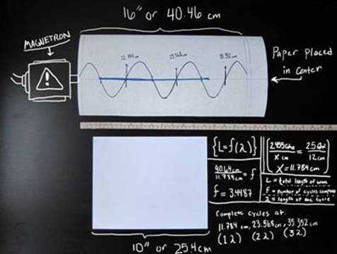
The fundamental concept of microwave radiation is standing waves, which are comprised of periodic directional shifts of electromagnetic energy. Standing waves can be calculated by using modified versions of sinusoidal functions. These can be modified to suit the amplitude, period, and x-y axis shifts of the wave. The known equation for a fixed-end standing wave is {L = f (λ)}. The ‘L’ variable signifies the total length of the standing wave, ‘f’ signifies the number of cycles completed in the total length, and signifies the length of a single cycle. The measured distance within the microwave can then be used to predict how many cycles the waves have completed, and whether any interference is caused by the reflecting wall. What I know is that both microwaves will be operating at 2455 Mhz across 16 inches (40.64cm). Using the equation for standing waves {L = f (λ)}, we will be able to determine and make predictions as to the affected areas of the waves. I’ve also included a step-by-step process and diagram of my predicted calculations. Included in the diagram is a scale (in cm and inches), as well as a sample paper and an illustrated side view of the microwave and magnetron.
{L=f (λ)}
[ L = Total length of standing wave ] [ 40.64 cm ]
[ f = Number of cycles completed in total length ]
[ λ = length of one cycle ]
[2.455 GHz cm=2.5 Ghz12 cm]
λ=11.784
[40.64=(f) 11.784]
f = 3.4487 cycles
The cycles begin at 0 cm, 11.784 cm, 23.568 cm, and 35.352 cm. Only the first three cycles are completed, however. Another cycle begins, and is reflected off of the opposite wall. (This will only be the case in the first round of tests.)
These tests will be run in a
standard, unmodified microwave on a regular setting. These will act as a group
of visual data to measure and compare to the predictions. I will place a wet
piece of paper in the microwave, first for thirty seconds, then for one minute,
and then for two minutes. This data will then be comparable to the results from
the second test.
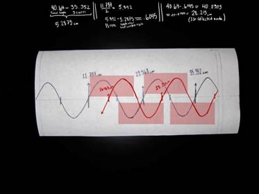
The reflected waves must be noted, as well. The total length of a wave leaving the cathode is 40.46 cm long, and there is still an incomplete cycle noted in the period. More calculations and a diagram are located below to aid the evidence of reflected wave interference. Located at right is a diagram showing the reflection of the electromagnetic waves and how they were calculated. The red areas are the destructive interference areas. These cause a loss of amplitude in the waves, yet increase the energy activity due to collision. The population of the waves does increase the excitement of the water molecules in food, but not without the presence of a wall to reflect them.
(40.64 cm-35.352 cm = 5.2875 cm)
( Total Cycle Length - Length of three cycles = remaining length of standing wave)
11.7842=5.892
1 cycle / 2 = .5 cycle
(5.892 cm - 5.2875 cm = .6045)
.5 cycle - remaining length of standing wave = remaining initial length of reflected cycle
(40.64 - .6045 = 40.0355)
Total cycle length - Remaining length of reflected cycle = First node of reflected waves
The other tests will be conducted in a microwave without a reflecting wall, in order to answer the question of whether the waves will be more effective in evenly heating the food. I will place three wet pieces of paper in for the same time increments as the first test. The second portion of tests will be to determine whether the destructive interference of the electromagnetic waves could be contributing to the uneven distribution of waves across microwave. If the patterns of residual moisture in the first group of tests is displaced less evenly than the patterns in the second group, a conclusion will be able to be reached.
Evaluation of Experiment ↑ TOP↑
According to the data, I can confirm that the affected areas in the first round of tests corresponded to the predictions I made, including the increasing population of reciprocating waves.
Upon removal of the paper from the microwave ovens, there was found to be a tremendous amount of residual heat left from the evaporated moisture. Longer activation times yielded greater internal heat. Since the airborne moisture did not seem to leave the compartment until removal, it was observed that it may act as osmotic heating mechanism which assists the temperature rise in food. This device may assist the retrieval of accurate results, as the affected areas of the paper will remain dry and isolated by the wetter unaffected areas.
Another factor which was also predicted was the reflective
properties of the opposite wall. The affected areas seem to populate the
farther end of the paper, which may be due to the intensity of the
electromagnetic waves. The additive population at first causes more intense
heat, but as the waves travel farther back, the destructive interference
decreases the amplitude of the waves.


|
30 seconds - No wall |
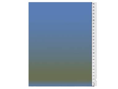
1 Minute - No wall |
2 Minutes - No wall |
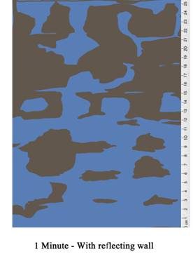
This was quite the opposite of the other tests’ results. Instead of having several heated areas, the affected areas were far less distinct from one another. The nature of the heating pattern seemed to be a gradient, beginning at the end closest to the magnetron, and losing heat towards the opposite end. The only affected areas similar to that of the first test were the area directly next to the magnetron.
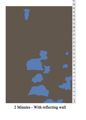
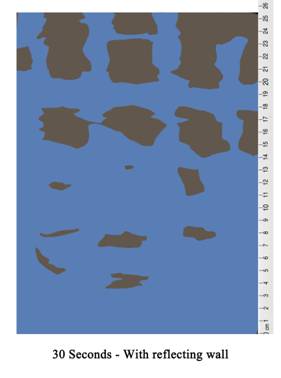
The last cycle is obstructed and reflected by the wall, causing the immediate population of electromagnetic energy on the far side of the microwave oven. I hypothesised that the reflecting wall would cause destructive interference with the reflected waves, which was confirmed in the end by the unaffected areas. The brown areas were the areas which were most affected by the magnetron, and no moisture could be found there. The blue areas are those where moisture remained after removal from the chamber, and had little to no change in heat.
The second round of tests was much different from the first. Upon removal, the paper samples were all still completely wet, with the exception of the last sample, which had a small dry area. All were much hotter to the touch, however. This may be due to the unaltered amplitude of the magnetron.
In the first round of tests, it was discovered that the reflecting wall had decreased the amplitude due to destructive interference, but increased the energy activity due to collisions. The difference in the second test is that the integrity of the standing waves was unaltered by reflected waves, and therefore became more effective in affected areas. The second round of tests did not include this feature, and therefore had only heated areas, and no dry areas.
The samples progressively gained total heat as they were exposed to the magnetron for longer periods of time. On the two minute sample, there was a dry spot located closest to the magnetron. No other distinctive data could be gathered in regards to the affected areas.
Analysis of data ↑ TOP↑
Because the mapped areas in the first round of tests included more conclusive data as to the nature of the wavelengths, there could be several consistencies noted in regards to the predictions. The predicted length of the standing waves was seen to be consistent in the tests, and when held side-by-side could be clearly seen. The wave interpretations seen on top match the pattern on the 1 minute test page. The test pages for the second round of tests resembled what was more of a map of heat from one side. The open side of the microwave must have been the cause of osmotic heat loss, heat which would have been held within a sealed microwave. The calculated predictions made about the reflected waves have been confirmed by the data. The population of the waves increases towards the opposite end of the microwave, and the destructive interference does affect the amplitude of the waves. One difference between the two tests is that the side closest to the magnetron in the second round of tests was more evenly heated than in the first round of tests.
Conclusive Results ↑ TOP↑
The results and measured data reflect the predictions made about the first test. The reflected waves are indeed an additive component of loss of even heating and moisture in the first round of tests. In the second round of tests, the paper was more evenly heated, but not as hot as the paper in the first round of tests. If one wanted to heat their food evenly, this problem could be solved by a rotating motor in the middle of a microwave with a non- reflective wall. However, the amount of heat distributed would take longer to reach the same temperature than in a microwave with a reflective wall. In essence, you must choose between getting your food fast and unevenly heated, or waiting patiently and getting an even heating pattern.
Limitations / Room for Improvement ↑ TOP↑
There were several challenges encountered during the process of the experiments. These included electrical failures in the microwaves, mechanical malfunctions with tools, and technical issues with computers. There were actually four microwaves that I purchased over the course of this experiment, and each time one failed, a total recollection of data was needed. In the end, only one worked until the end of the experiment. Equipment limitations began at having no equipment to detect electromagnetic radiation. The tools used to disassemble the microwave devolved from power drill to screwdriver to pliers. Each one proved less worthy for the job along the way, and were needed again to disassemble the next microwave after one failed. In the end, working and re-designing the experiment each time streamlined the process, which benefitted the collection of data. So I got that going for me, which is nice.
This investigation has answered many questions about the curiosities of the microwave. Its challenges which were once a mystery to me became second-hand knowledge as the experiment progressed. Magnetrons may have many other uses which people are not yet aware of, and this experiment proved that they have more potential than just a device which quickens the process of heating food.
-
Wikipedia: The free encyclopedia: Cavity Magnetron
; Fundamental (and open-source)
information about the cavity magnetron. It has lots of helpful links to great
studies, as well.
-
Influence
of Implementing Straps on pulsed relativistic Magnetron Operation;
A study done by the University of
New Mexico’s physics department on how straps affect the movement of electrons
through the magnetron while it is operating.
-
‘Microwave
cam.com’ (Cool videos of things in a microwave… so you don’t have to.)
Some person was smart enough (or
dumb enough) to put things in microwaves and watch plasmids form on them.
-
BBC
Article: ‘The Briefcase that Changed the World’:
A short article about the
conception of the magnetron and how it influenced World War II.
-
(For
those of you who read Czech) Czech
Digital Mathematics Library: New method of developing unhampered oscillations A PDF document which includes
helpful formulas when trying to observe electromagnetic waves.
Bibliography:
1. "The Magnetron." Magnetron Operation. Physics Department; Georgia State University, n.d. Web. 15 Nov. 2016.
2. "Radar Recollections - A Bournemouth University / CHiDE / HLF Project." The Magnetron. N.p., n.d. Web. 17 Nov. 2016.
3. “The Physical Review.” The Effect of a Magnetic Field on the Motion of Electrons between Coaxial Cylinders. Albert Wallace Hull; Harvard University Publishing, January 1921. Text. 13 Nov. 2016.
4. "Related Information; Cavity Magnetron." The MIT 150 Exhibition. N.p., n.d. Web. 11 Nov. 2016
5. "Magnetron." Encyclopedia Britannica Online. Encyclopedia Britannica, 4 July 2016. Web. 09 Nov. 2016.
6. "Henry Ott Consultants." Frequency - Wavelength Chart. N.p., n.d. Web. 01 Jan. 2017. <http://www.hottconsultants.com/techtips/freq-wavelength.html>.