The Effect of Barrel Length on Projectile Velocity in a Pressurized Air Cannon
by Davinder Jhattu & Louise Clark - 5/29/14
Table of Contents
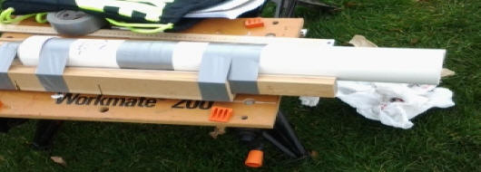
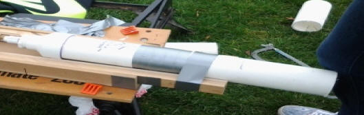
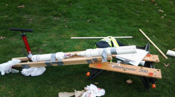
Photos of various barrel lengths, setup, and executing the experiment
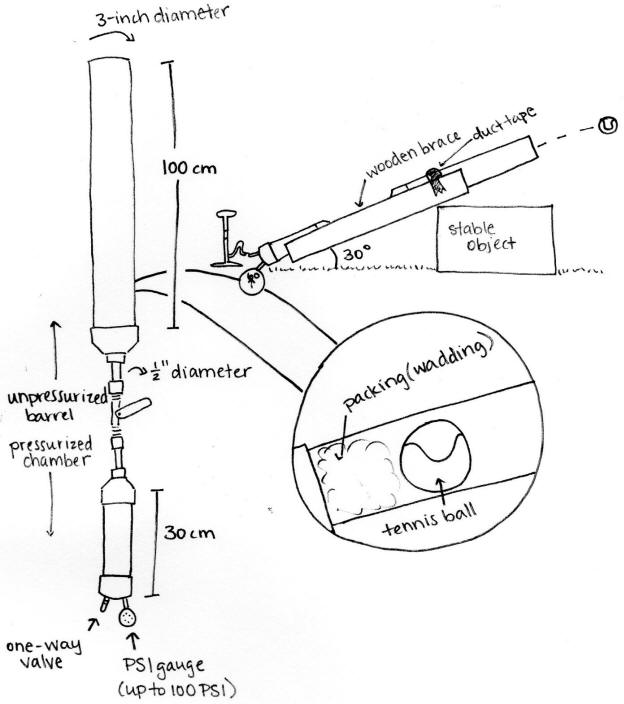
A pressurized air cannon relies on several factors in order to shoot a projectile in a straight line for any distance. First, there must be a tightly sealed chamber into which pressurized air may be pumped through a one-way valve. This chamber must be connected to a valve with a smaller circumference than both the pressure chamber and the connecting barrel. A projectile is loaded into the barrel, which is in turn shot by the release of pressurized air into the barrel. The purpose of the conducted investigation was to determine whether the length of the aforementioned barrel affects the distance the projectile can achieve as measure in velocity. In order to conduct this experiment, all other factors besides barrel length must be kept at as constant a level as possible. These factors include but are not limited to the pressure to which the air inside the pressure chamber reaches, the angle that the cannon forms with level ground when shot, air temperature, and projectile launched.
The initial hypothesis regarding this investigation was that a cannon with a longer barrel length would lead to a powerful launch of the given projectile. Barrel length and velocity are directly related and affect how fast an object is projected from an air cannon. The premise this investigation is based on relies on the premise that a longer barrel length will create a higher velocity for the following reason. We know this since when a projectile is set in motion by the initial energy potential, the air expands within the barrel causing the projectile to speed up as the pressure builds. So, when the barrel length is longer, a projectile will be expelled faster as more pressure is built up. Barrel length is defined as the distance between the pressurized air chamber and the open end of the cannon. This distance is measured in centimeters and will be gradually shortened as the experiment progresses. Distance is defined as the first bounce of the projectile. The independent variable, barrel length in centimeters, will be used to record the dependent variable, distance, which will in turn be used to calculate velocity.
Once the cannon itself has been built, fix it at a set angle (around 30 degrees with the ground) and pack the barrel with a wad of non-porous material such as plastics bags. On top of this wad, place the projectile. Using a manual bike pump or automatic air compressor, pump through the valve into the pressure chamber until the PSI meter reads 80 PSI. Quickly release the ball-socket valve and record the distance away from the cannon that the projectile makes first contact with the ground. Repeat this process for three trials at each variation: barrel lengths of 100cm, 80cm, 60cm, 40cm, 20cm.
|
1.5 meters of 3� diameter PVC pipe |
One PVC cap |
Two 1/2� male adapters |
|
I 1/2� ball-socket valve |
Roll of duct tape |
Hacksaw |
|
Bike pump |
100 psi pressure gauge |
Tire valve |
|
Portable work bench |
Plastic bags |
One tennis ball |
|
Meter stick |
Two 3� to 1/2� pipe converters |
Wood to build support brace (2 x 4 will suffice) |
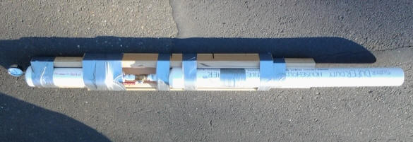
100 cm Barrel
80 cm Barrel
60 cm Barrel
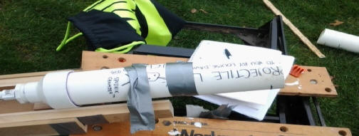
40 cm Barrel
20 cm Barrel
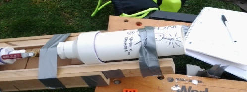
Our setup - air cannon resting at 30against workbench
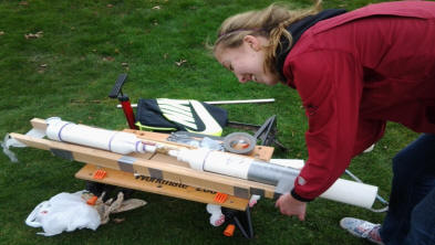
Louise taping the cannon to the brace
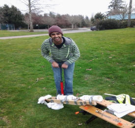
Davinder pumping up the air chamber
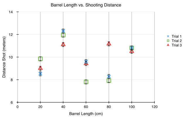
This data table was calculated by taking the number of steps to reach the first bounce of the projectile and multiplying that number of steps by .6 meters, so the equation was: Range (m) = number of steps(.6)
|
Trial |
100 cm Barrel Length Range (m) (� .2m) |
80 cm Barrel Length Range(m) (� .2m) |
60 cm Barrel Length Range (m) (� .2m) |
40 cm Barrel Length Range (m) (� .2m) |
20 cm Barrel Length Range (m) (� .2m) |
|
1 |
10.8 |
8.28 |
9.6 |
12.3 |
8.52 |
|
2 |
10.8 |
7.92 |
7.8 |
11.94 |
9.84 |
|
3 |
10.5 |
11.16 |
9.42 |
11.1 |
9 |
|
Average |
10.7 |
9.12 |
8.94 |
11.78 |
9.12 |
To get the velocity of the projectile, the raw data was placed into the
following equation:
Velocity (m/s) (unknown) = Range(9.81)sin(π3)
|
Trial |
100 cm Barrel Length Velocity of Projectile (m/s) (� .2m/s) |
80 cm Barrel Length Velocity of Projectile (m/s) (� .2m/s) |
60 cm Barrel Length Velocity of Projectile (m/s) (� .2m/s) |
40 cm Barrel Length Velocity of Projectile (m/s) (� .2m/s) |
20 cm Barrel Length Velocity of Projectile (m/s) (� .2m/s) |
|
1 |
11.06 |
9.68 |
11.06 |
11.80 |
9.82 |
|
2 |
11.06 |
9.47 |
11.06 |
11.63 |
10.56 |
|
3 |
10.91 |
11.24 |
10.91 |
11.21 |
10.10 |
|
Average |
11.01 |
10.13 |
11.01 |
11.55 |
10.16 |
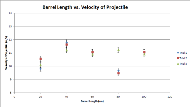
The results of our investigation showed that the farthest range the projectile (tennis ball) was shot was 12.3 meters with a 40 cm barrel length and the greatest velocity was 11.80m/s. The shortest distance shot was at 60 cm barrel length with a distance of 7.8 meters and velocity of 9.47m/s, yet the shortest barrel length, 20 cm, had a higher average distance shot than at the 60 cm variant. The results show that the greatest shooting distance and greatest velocity are with a 40 cm barrel.
Our data did not support our hypothesis that with decreased barrel length, the projectile would have a decreased velocity as there is less length for velocity to build. Our investigation did not show this and as a result, our hypothesis has been disproven. The data did show a decrease from 100 cm to 60 cm barrel length, which corresponds to our hypothesis, but the greatest average velocity (11.55 m/s) and greatest velocity (11.80 m/s) was at 40 cm barrel length which counters what our hypothesis is based upon.
Since we expected for their to be more velocity with a longer barrel as the air would have a longer distance to expand in the barrel, a 100 cm barrel would, hypothetically, shoot with the greatest velocity. As this did not happen, our data indicates that it is possible to have a barrel that is too long. Based off of the assumption of having a barrel that is too long, there is a maximum velocity threshold the air in the barrel can reach and after that threshold has been met, the velocity rebuilds to the threshold as the barrel continues. This threshold seems to be nearly reached at an optimal 40 cm barrel length giving the projectile a maximum velocity and therefore maximum distance.
The cannon used did not shoot to the range we expected. We expected the cannon to shoot at around 85 meters, but the cannon shot the projectile a mere 11.78 meters at most, which is substantially less than the expected outcome, which may be attributed to leaks in the pressure chamber causing less than desired air pressure in the cannon.
As mentioned above, the cannon did not shoot to the distance expected and that could have been caused from errors. These errors include errors in design and launching. The design of the cannon required some caps to be epoxied to the PVC pipes. Despite using a bonding agent that chemically alters the PVC to fit the cap, some gaps and areas for air to escape were present as hissing and a steady drop in air pressure as the air chamber was being filled to 60 psi, confirm that error. As this error persisted through each trial, it made it possible for the cannon to be launched at inconsistent pressures; in other words, one trial for a single variant could have been launch at 62 psi while a second trial for the same variant could have been launched at 59 psi. Another error was the type of valve used. We used a ball-socket valve which could have allowed a slight loss in air pressure with each trial as the opening of the valve is not instantaneous. With this valve, launching would be another main source of error in conjunction with the steady loss of air pressure as full focus on quickly opening the valve could not be maintained since partial focus had to be kept on the pressure gauge and when it was at 60 psi. One final error is the projectile used. A tennis ball has a furry exterior which caused increased air friction and friction within the barrel resulting in decreased distance and velocity.
If this investigation were to be tested again, a tighter seal around the caps, pump valve, and pressure gauge would be tested for a complete seal before trials took place. This would ensure maximum air pressure could be obtained without the potential for a loss in air pressure resulting in a shooting distance at the incorrect pressure. For the release valve, a more instantaneous valve, such as a pneumatic valve, would be used to ensure minimal air pressure is lost when launching the projectile in order to obtain a maximum shooting distance. We would also change the projectile to a lacrosse ball as it has a smooth outer surface and would lessen the air friction and friction within the barrel.
1. "The Truth About Barrel Length, Muzzle Velocity and Accuracy | The Truth About Guns." The Truth About Guns | Exploring the ethics, morality, business, politics, culture, technology, practice, strategy, dangers and fun of guns. N.p., n.d. Web. 29 May 2014. <www.thetruthaboutguns.com/2013/10/daniel-zimmerman/the-truth-about-barrel-length-muzzle-velocity-and-accuracy/>. -- An independent study conducted by a gun enthusiast and the results of his investigation.
2. "The Effects of Barrel Length on the Range of a Projectile Fired From A Pneumatic Cannon." TuHS Physics Home Page 1.1. N.p., n.d. Web. 29 May 2014. <www.tuhsphysics.ttsd.k12.or.us/Research/IB03/HamlGreeSteph/index.HTM>. -- This link was a project, similar to what we conducted, done by previous Tualatin High School IB Physics II students.
3. "SWAT Article BARREL LENGTH." Tactical Operations Inc. N.p., n.d. Web. 29 May 2014. <www.tacticaloperations.com/SWATbarrel/>. -- This article discusses barrel length and its effect on barrel length in relation to utilizing high-powered rifles during SWAT situations.
4. "Why Shorter Rifle Barrels May Be Better | Field & Stream." Field & Stream. N.p., n.d. Web. 29 May 2014. <www.fieldandstream.com/blogs/gun-nuts/2012/02/why-shorter-rifle-barrels-may-be-better>. -- This is an article supporting the notion that the shorter the barrel of a rifle, the greater the accuracy of the weapon.
5. "How To Build a Generic Air Cannon." Instructables.com. N.p., n.d. Web. 29 May 2014. <www.instructables.com/id/How-To-Build-a-Generic-Air-Cannon/>. -- This article was essential in aiding the design of our air cannon.
6. "Compressed Air Tennis Ball Mortar." Instructables.com.
N.p., n.d. Web. 29 May 2014. <www.instructables.com/id/Compressed-Air-Tennis-Ball-Mortar/>.
-- Another cannon design we considered when in the design phase of our
investigation, but did not pursue.