What relationship, if any, exists between eddy current damping and velocity in a simple aluminum track system?
Table of Contents: Introduction Design Data Collection & Processing Conclusion References/Further Reading Go Up [Other TuHS Research]
 Beginning physicists tend to think of
induced currents only within the context of changing solid metal structures
that are immersed in a magnetic field larger than the given structure. But what
if the magnetic field is only applied in a small portion of a metal structure?
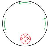
Consider a rotating metal cylinder with a magnetic field applied “into the
page” in a small circular portion (left).[i]
Beginning physicists tend to think of
induced currents only within the context of changing solid metal structures
that are immersed in a magnetic field larger than the given structure. But what
if the magnetic field is only applied in a small portion of a metal structure?
Consider a rotating metal cylinder with a magnetic field applied “into the
page” in a small circular portion (left).[i]
 Because the metal cylinder is rotating,
it induces an electromotive force (emf) in the area of the applied magnetic
field. Lenz’s law states that an electric current induced by a changing
magnetic field will flow such that it will create its own magnetic field that
opposes the changing magnetic field.[ii]
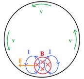
The current flows upward in the magnetic field (and completes a downward loop
outside of the field) because it opposes the emf-generated current. On the left
side of the loop, the induced current flows counterclockwise to generate an emf
out of the page that opposes the increase in magnetic flux into the page; and
on the right side of the loop, the induced current flows clockwise to generate
an emf into the page that opposes the decrease in the inward magnetic flux.
These currents are called eddy currents, and in the rotating system, the emf
produced generates a force to the left that opposes the motion of the conductor
itself.
Because the metal cylinder is rotating,
it induces an electromotive force (emf) in the area of the applied magnetic
field. Lenz’s law states that an electric current induced by a changing
magnetic field will flow such that it will create its own magnetic field that
opposes the changing magnetic field.[ii]
The current flows upward in the magnetic field (and completes a downward loop
outside of the field) because it opposes the emf-generated current. On the left
side of the loop, the induced current flows counterclockwise to generate an emf
out of the page that opposes the increase in magnetic flux into the page; and
on the right side of the loop, the induced current flows clockwise to generate
an emf into the page that opposes the decrease in the inward magnetic flux.
These currents are called eddy currents, and in the rotating system, the emf
produced generates a force to the left that opposes the motion of the conductor
itself.
What relationship, if any, exists between eddy current damping and velocity in a simple aluminum track system? In real life, eddy currents can be used in transportation systems like monorails or inner-city rapid transit cars on rails to generate a stopping force.[iii] An electromagnet generates a magnetic field that flows through the metallic rails or wheels and opposes the car’s motion. If this principle is applied to an aluminum glider while the glider accelerates on an aluminum track system, what is the effect on the glider’s velocity? Is the graph of velocity as a function of the force of the eddy current logarithmic, linear, or exponential? Does the fact that we utilize permanent magnets (hard drive magnets) instead of powered electromagnets influence our results?
We hypothesized that the graph of velocity as a function of the force of the eddy current would be logarithmic. As the force of the eddy current increased, the velocity would slowly stop increasing. Controlled variables included the initial velocity (0), even when the air pump was levitating the glider slightly above the track, as well as external and surface temperatures. The independent variables were the force applied to generate motion and the corresponding strength of the eddy current, and the dependent variable was velocity. We assume a uniform magnetic field, the absence of which has caused anomalies in conductors such as cylinders.[iv]
Design [<--] [-->]
Our experimental procedure needed to include ways of measuring eddy current as well as velocity. Also, it needed to include a calculated, consistent amount of force at different magnitudes so that we could measure the opposing force of the eddy currents at varied velocities.
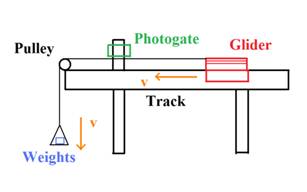
 The materials used were an aluminum air
track system (glider and track with air pump) approximately 1.5 meters long; a
photogate position monitor; a frictionless pulley along with mounting
materials; a barrier to stop the glider at the end of the track; a frictionless
pulley system (thin wire, frictionless wheel); numerous masses that could be
combined to produce a variety of weights; and two hard drives on either “leg”
of the glider parallel to the track. The setup is illustrated below.
The materials used were an aluminum air
track system (glider and track with air pump) approximately 1.5 meters long; a
photogate position monitor; a frictionless pulley along with mounting
materials; a barrier to stop the glider at the end of the track; a frictionless
pulley system (thin wire, frictionless wheel); numerous masses that could be
combined to produce a variety of weights; and two hard drives on either “leg”
of the glider parallel to the track. The setup is illustrated below.
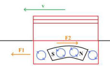
As soon as the wire is released and weight is applied to the end of the pulley, the glider begins to accelerate forward. However, as it does, eddy currents are produced by the changing area of the magnetic field generated by the hard drive magnets. They create a counterforce on the glider’s motion in a direction opposite to that of the conventional motion produced by the product of the mass of the weights and gravitational acceleration.
Note that there is no mechanical load on the system, but it still reaches a maximum velocity after a certain time. This is because the strength of the eddy current increases proportionally with the change in area, which corresponds to the velocity of the glider. Thus the glider can only accelerate to the point at which the backward force of the eddy current is equivalent to the force produced by the mass of the weights times the gravitational acceleration.
Assuming any
friction between the glider and the track as well as air friction are
negligible, we can set up a rough model without knowing exact quantities. The
magnitude of the external force to the left,
![]() must balance the eddy current force to the right,
must balance the eddy current force to the right,
![]() .
The induced current
.
The induced current
![]() is
equivalent to voltage divided by resistance, where the voltage is the back emf
given by
is
equivalent to voltage divided by resistance, where the voltage is the back emf
given by
![]()
and so
![]()
Since B
(constant because of permanent hard drive magnets), l (the glider’s legs
do not change), m (no mass is added from
![]() ),
g (gravitational acceleration is virtually constant) and R (we
assume the parallel rails have negligible resistance) are all constant,
),
g (gravitational acceleration is virtually constant) and R (we
assume the parallel rails have negligible resistance) are all constant,
![]()
This means that after some critical time t is reached, the change in velocity with respect to time (acceleration) becomes zero, so the constant application of an external force produces a maximum velocity after some time t.
With this conceptual model in mind, our investigation focused on examining this relationship between applied force and maximum velocity.
Data Collection and Processing [<--] [-->]
As the glider moved through the photogate, we recorded its maximum velocity along with the amount of mass we had placed on the end of the pulley. (We were able to determine these quantities because the glider had already reached maximum velocity before it had hit the photogate.) The data is summarized below.
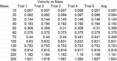
Data file: text [.txt] .:. excel [.xls]
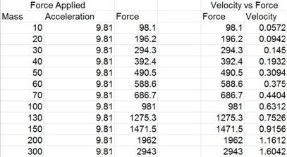
Remember that because the force of the eddy current was equivalent to the acceleration due to gravity after a critical time had been reached, we are able to measure the effects of the eddy currents in Newtons.
In analyzing the data, we determined that because force was calculated from mass times acceleration, all of the uncertainty must stem from the mass. We determined that the mass had an uncertainty of a tenth of a gram, or one decigram (dg), and therefore was negligible.
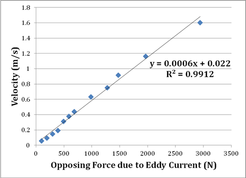
Our hypothesis was not confirmed by the data we gathered. Ultimately we decided that our experimental design produced accurate results but was limited in scope. For example, one might suggest that a logarithmic pattern begins around 1500 N. However, the unusually high r-squared value of the linear trendline suggests that the results were conclusively linear.
The most significant improvement to the experiment that might still yield a logarithmic result is increasing its scale. While we explore the effects of adding pounds, real-world transportation systems are affected by the addition of tons. Perhaps the glider was too small of a test mechanism and had not yet reached a critical mass at which it would negate the effects of air resistance. Additionally, while we utilized hard drive magnets with permanent levels of eddy current potential, the use of electromagnets would significantly enhance this research project because we could measure how eddy currents quickly ramped up would directly affect the velocity. A second major improvement to analysis of the data would be obtaining precise measurements of all dimensions involved. At what exact time does the glider reach its maximum velocity over several trials of increasing external force? What is the exact strength of the hard drive magnets compared to other magnets, and is this system practically scalable? Of these, the technology to determine precise timing is readily available. Finally, lengthening the distance between the measuring point and the initial release point on the track might help us ensure that there were no errors due to friction with the track, or the effects of air resistance did not significantly prolong the time it took to reach maximum velocity. Our experimental design is only inherently limited by the fact that the string has mass, the pulley may not be entirely frictionless, and slight errors may have been caused by air resistance and friction with the track.
Justification for expanding the scale of the experiment comes from the research of Jürgen Prem, Stefan Haas, and Klaus Heckmann, who conclude that the eddy current brake is unusable at low speeds, but can be used at high speeds both for emergency braking as well as regular and regulated braking.[v] Ultimately, the truest expansion of the scale is real-world testing on roller coasters[vi] and transportation systems, where these braking systems may already be perfected. Moreover, these real-world systems may already use both permanent magnets and electromagnets, as Kitanov and Podol’skii found that the most effective braking action occurs with the use of dedicated magnetic pieces that combine magnetic rail braking and eddy current braking.[vii]