The Guillotine
A Series of Unfortunate
Beheadings
Jennifer Conner
Table
of Contents:
Introduction
.:. Review of Literature .:. Statement
of the Problem .:. Hypothesis .:. Materials
.:. Method .:. Results .:. Uncertainty
.:. Graph .:. Discussion
.:. Sites to Execute .:. Bibliography
.:. Return to Research Page
Introduction:
 The guillotine has had a mysterious, albeit gruesome, history. Dr. Joseph-Ignace
Guillotine did not invent the guillotine, but his name has been associated with
the machine because “he was the one to propose that a mechanical device carry
out the death penalty” (Fabricius). In addition, Dr. Antoine Louis, Secretary of
the French College of Surgeons, is credited as the actual designer of the
guillotine (Benet 413).
The guillotine has had a mysterious, albeit gruesome, history. Dr. Joseph-Ignace
Guillotine did not invent the guillotine, but his name has been associated with
the machine because “he was the one to propose that a mechanical device carry
out the death penalty” (Fabricius). In addition, Dr. Antoine Louis, Secretary of
the French College of Surgeons, is credited as the actual designer of the
guillotine (Benet 413).
The guillotine does not have a concrete place in today’s modern world as a mode
of execution. The last recorded execution using a guillotine was in France,
during 1977, after which, capital punishment was outlawed (in all forms).
However, the first guillotine machines date back to the 13 00’s A.D., nearly 400
years before the French Revolution would make guillotines famous. One of the
first recorded executions with a guillotine-like machine was in 1307 A.D. in
Ireland. The drawing on which the account is based, called, “The Execution of Murcod Ballagh,”
(right) clearly shows a straight blade in contrast to the oblique ones
of the later time periods (Fabricius). The Halifax Gibbet and The Maiden, famous
guillotine-like machines in the 15th and 16th centuries, were fashioned with
rounded blades. It wasn’t until 1792 (left) that an oblique blade was tried and made
effective as a means of execution. Further advancements to the machine include a
new release mechanism (Leon Berger) and a shield to hide the blade (Nicolas Roch).
00’s A.D., nearly 400
years before the French Revolution would make guillotines famous. One of the
first recorded executions with a guillotine-like machine was in 1307 A.D. in
Ireland. The drawing on which the account is based, called, “The Execution of Murcod Ballagh,”
(right) clearly shows a straight blade in contrast to the oblique ones
of the later time periods (Fabricius). The Halifax Gibbet and The Maiden, famous
guillotine-like machines in the 15th and 16th centuries, were fashioned with
rounded blades. It wasn’t until 1792 (left) that an oblique blade was tried and made
effective as a means of execution. Further advancements to the machine include a
new release mechanism (Leon Berger) and a shield to hide the blade (Nicolas Roch).
The improvements to the guillotine highlight important facts relating to testing
of the blade. Namely, the blade transitioned from a solid slab, which was more
effective in breaking a person’s neck, to a slanted blade, which behaved like a
sword.
Due to the fact that there is little recorded history of the machines between
the fourteenth and eighteenth centuries, questions arise as to why the angle of
the blade was changed. But most of these questions focus around a single query:
Is an oblique blade more efficient than its parallel counterpart?
TOC
Review of Literature:
There have been no comprehensively recorded studies of the guillotine itself, as
any improvements were made before the 19th century. The evolution of the blade,
one of the few variables involved with the guillotine, was altered to make the
device more efficient. This goal was met and the design has remained nearly
unchanged through the 19th, 20th, and 21st centuries.
TOC
Statement of the Problem:
The purpose of this experiment was to determine if an oblique blade was more
efficient than one that was straight. The Dependent variable is the angles of
the blades while the Independent Variable is the different heights the blade was
raised.
TOC
Hypothesis:
The blades with an angle, specifically between forty-five and seventy-five
degrees, will be the most efficient (slice through the most clay at the lowest
height) because the force of the blade will hit a smaller area, thus slicing the
clay better.
TOC
Materials:
• Milk Crate
• Hollow Metal Rod approx 1.3m (cut into 2 (.54m) sections and 2 (.10m)
sections)
• .1016m (width) piece of metal .1524m long
• Wood Block 6cm x 2.81cm with a 2.mm wide (2 cm deep) cut across the top
• 6 razor blades
• Ruler
• Modeling Clay
• Protractor
TOC
Method:
The first step was to establish the basics; determine how to measure
“efficiency”, what type of setup to use, find what angles of the blades to test,
and create a procedure.
 Although initial/practice testing demonstrated that the oblique blades seemed to
be better than the straight one, there needed to be an empirical way to show
such results. Because modeling clay was one of the original substances that was
used for testing the blade, it seemed plausible that it could be used as a part
of the experiment. During mini-trials, it was noticed that when the blades did
not slice all the way through the clay, a smooth indentation was left. Thus, the
progress of the blade could be measured by how far it sank into the clay. In
order to relate that measurement to the efficiency of the blades, the blade
could be dropped from different heights. If the oblique blades were more
efficient than the straight one, then they would slice through the clay deeper,
at lesser heights.
Although initial/practice testing demonstrated that the oblique blades seemed to
be better than the straight one, there needed to be an empirical way to show
such results. Because modeling clay was one of the original substances that was
used for testing the blade, it seemed plausible that it could be used as a part
of the experiment. During mini-trials, it was noticed that when the blades did
not slice all the way through the clay, a smooth indentation was left. Thus, the
progress of the blade could be measured by how far it sank into the clay. In
order to relate that measurement to the efficiency of the blades, the blade
could be dropped from different heights. If the oblique blades were more
efficient than the straight one, then they would slice through the clay deeper,
at lesser heights.
The setup needed to be designed with precision in order to minimize friction
while maximizing usage. The initial guillotine design was built inside a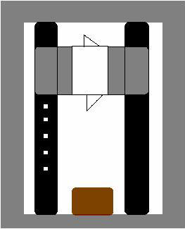 .3048meter x .5334m crate that would stabilize the structure. Next, two metal
rods were measured (.54864m); these would serve as the “tracks” to which the
blade apparatus was attached. The casings (10.16cm) that went over the two metal
rods fit well; there was less than a millimeter clearance between the two. This
helped minimize “rattling”, or excess movement, by the blade, while not creating
a substantial amount of friction. The casings that slid up and down the metal
“tracks” were also sanded on the edges and about one inch into the tube. This
was done because the casings were cut from a hollow metal bar; by sanding it
reduced or eliminated the metal shavings that remained. The casings were
attached on the front and back with two pieces of lightweight wood via hot glue.
Next the blade apparatus was put on the “tracks”, and the metal rods were
secured in place. A “chopping block” was held to the bottom of the guillotine;
it had a 2.5 millimeter cut across in order to catch the blade. It was 6
centimeters long and 3.81cm tall. The blade would be attached by metal clips
that would hold it to the sliding apparatus. Measurements were also drawn along
the side in order to test the hypothesis. After multiple tests, this setup
seemed to work okay. However, problems were encountered; the metal clips did not
always hold the blade on, none of the sharp blades (straight or oblique) were
cutting through the clay, and it was difficult to place the blade in the same
position every time. Thus, the decision was made to go to a metal design. The
same steps were used, from the metal rods to the blade device. The difference
was that the there was a piece of thin sheet metal (attached to the casings by
zip ties) that the blades would attach to via two screws. This gave the blade
more force (increased mass) and assured that the blade was held securely in
place in the same position. This design also allowed for two blades to be
attached on plate. This was especially important as there were only limited
materials available.
.3048meter x .5334m crate that would stabilize the structure. Next, two metal
rods were measured (.54864m); these would serve as the “tracks” to which the
blade apparatus was attached. The casings (10.16cm) that went over the two metal
rods fit well; there was less than a millimeter clearance between the two. This
helped minimize “rattling”, or excess movement, by the blade, while not creating
a substantial amount of friction. The casings that slid up and down the metal
“tracks” were also sanded on the edges and about one inch into the tube. This
was done because the casings were cut from a hollow metal bar; by sanding it
reduced or eliminated the metal shavings that remained. The casings were
attached on the front and back with two pieces of lightweight wood via hot glue.
Next the blade apparatus was put on the “tracks”, and the metal rods were
secured in place. A “chopping block” was held to the bottom of the guillotine;
it had a 2.5 millimeter cut across in order to catch the blade. It was 6
centimeters long and 3.81cm tall. The blade would be attached by metal clips
that would hold it to the sliding apparatus. Measurements were also drawn along
the side in order to test the hypothesis. After multiple tests, this setup
seemed to work okay. However, problems were encountered; the metal clips did not
always hold the blade on, none of the sharp blades (straight or oblique) were
cutting through the clay, and it was difficult to place the blade in the same
position every time. Thus, the decision was made to go to a metal design. The
same steps were used, from the metal rods to the blade device. The difference
was that the there was a piece of thin sheet metal (attached to the casings by
zip ties) that the blades would attach to via two screws. This gave the blade
more force (increased mass) and assured that the blade was held securely in
place in the same position. This design also allowed for two blades to be
attached on plate. This was especially important as there were only limited
materials available.
The final step was to determine which angles to use. Zero degrees was clearly
needed; however, the other oblique angles would be harder to choose. Due to
limited materials, only six angles, in total, could be used. After looking at
various angles on a protractor, five representative angles were chosen: 0
degrees, 30 degrees, 45 degrees, 75 degrees, and 90 degrees. With one angle
option left, a miniature test was done to see where another angle would fit in.
Because the 45 and 75 degree angles cut the farthest into the clay, a 60 degree
angle was chosen in hopes of being better than both. The blade angles were
drawn, with a protractor, onto the plate that attached to the blade apparatus.
The blades were then hot-glued into place, with all blades extending 1.5 cm from
the sliding part.
Thus, all of the materials were ready. The procedure was simple; the guillotine
would be raised to a mark (from 4.445cm to 29.84cm) and released where it would
hit a 1.5x1.5x1.5cm clay cube. The same piece of clay was used for all trials,
and was reworked into a cube for each trial. This kept the clay limber and at a
similar temperature for each test. After each drop, the blade was quickly lifted
to help avoid the sheer mass of the sliding apparatus from pushing the blade
deeper. Next, a ruler would measure how far into the clay the blade had fallen.
Eleven different heights were used for the six angles.
TOC
Results:
Raw Data
(The height measurements are exact because it was originally measured in inches.
The numbers were simply converted)
TOC
Uncertainty:
There are three possible uncertainties in this experiment. The first is the
angles of the blades. The angles were found using an equipment protractor (it
was a medium scaled one) and drawing onto the metal sheets. The uncertainty
would most likely be plus or minus two degrees, as the increments were ten
degrees apart. The next uncertainty it for the height at which the blade was
dropped. In order to measure the distances, a tape measure was used. However, it
was marked while it was in position, probably making some of the measurements
plus or minus two centimeters. The last uncertainty is the most important. It is
the amount of clay sliced through. The main problem here is that because the
blades only came down 1.5cm, there was opportunity for the metal plate holding
it to hit the clay. This would smash the top part of the clay. This is
important, as when the indentation was measured, the smashed part may be
overlooked and a smaller amount of material would be recorded as sliced.
TOC
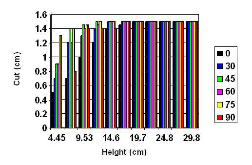
Graph of Data:
TOC
Discussion:
As evident in the data table, my hypothesis is well supported. In my hypothesis,
I stated that not only the blades with an angle would fare better than the zero
degree angle, but that the angles between 45 and 75 would be the most efficient.
In the data table, the angled blades were able to slice through the clay at
least seven centimeters before the zero degree angle. The 45 and 75 degree
angles were the first to cut through the clay after a 12.065cm drop. My initial
reaction to this was that the 60 degree angle would therefore be the best
because 60 is the average of the two. However, this was not the case; the 60
degree angle cut through the clay 2 cm after the 45 and 75 degree angles. The 30
degree angle did as well as I expected it to, while the 90 degree one took me by
surprise. It seemed unusual that it would cut through the same amount of
material at three different heights, but I retested it, and received the same
results. The zero degree angle also performed how I thought it would. It tended
to smash the area around the cut more than any other angle. The uncertainty here
is probably the greatest among any of the other blades because, as
aforementioned, the metal sheet that the blade attached to could also hit the
clay. Therefore, those numbers would be lower. It is also interesting to note
that after a certain height, (19cm), all the blades were able to slice through
the clay.
To make sure the results contained fewer errors, I tested the angles randomly.
This was done because I was working with clay, and it tended to be slightly hard
at first. Nevertheless, the more I worked with it, the more it stabilized. I
also tried to avoid errors in measuring, so I used a range of rulers (some
small, some big) in order to get the closest to the correct measurement.
Nonetheless, I could have erred in other ways, such as: the lack straightness of
the angle on the blade apparatus, dullness occurring in the blades, the chopping
block cut that caught the blade could have been too wide (causing more smashing
than slicing), and there could have been excess friction between the “tracks”
and the casings.
To put these findings in a historical setting, I think that the blades did
change due to a need for more efficiency. With oblique blades cutting through
more at a lesser height, it would be more economical for executioners to use
this style.
To further research in this field, I would look at the force that the blades
exert onto on object. This could potentially improve the efficiency of the less
oblique blades due to more mass. Also, the length and width of the blade exposed
could be another type of experiment done; this may improve the amount sliced as
the blade could make a clean cut without any smashing. Most pictures of
guillotines show that the blade is merely held with a rope, where it is both
long and wide. It may also be interesting to test the guillotine with higher
height numbers, although after a while, one may run into friction errors and
uncertainties.
TOC
Sites to Execute
http://www.metaphor.dk/guillotine/Pages/Guillot.html
- This site is probably the most reliable and
the most thorough of any of the sites I found and it has information on all
areas of the guillotine.
http://europeanhistory.about.com/cs/frenchrevolution/a/Guillotine.htm
- This site has a very lengthy history of the
guillotine and serves those most interested in the development of weapons in
general.
TOC
Bibliography:
Author Unknown; Benet’s Reader’s Encyclopedia; Edition 3, 1987; New York; p. 413
Author Unknown; U.S. News & World Report; July 17, 1989; Volume 107, N. 3;
pp.46-9
Author Unknown; Guillotine; October 25th, 2005; http://en.wikipedia.org/wiki/Guillotine
Fabricius, Jorn; The Guillotine Headquarters; October 24th, 2005; http://www.metaphor.dk/guillotine/Pages/Guillot.html
Wilde, Robert; The Guillotine; October 25th, 2005; http://europeanhistory.about.com/cs/frenchrevolution/a/Guillotine.htm
TOC
Return to Research Page