Research Project: The Physics of Catapults
Return to Research Page| Research Question| Background| Hypothesis| Preparation| Experiment| Procedure| Raw Data| Graphs| Conclusion| Works cited| Links
Research Question:
Back to top
What is the effect of moving the fulcrum of the catapult forward and backward? At which distance from the middle of the plank does the weight fly highest?

Background:
Back to top| Projectile
Motion| Angular Mechanics| Potential
Energy|
Projectile Motion Back
to top| Back to Background
There are three basic assumptions
in analyzing the projectile motion of an object launched by a catapult:
1)
Acceleration
due to gravity is constant and directed downward. In this case the acceleration due to gravity will equal 9.8
m/s/s.
2)
The
effect of air resistance is negligible
3)
The
surface of the earth is a stationary plane, which therefore means that the
curvature of the earth’s surface and the rotation of the earth are negligible.
To analyze the projectile motion of an object, the two-dimensional motion must be separated into horizontal and vertical components. The vertical component is where the object undergoes constant acceleration due to gravity, which has a magnitude of g = 9.80 m/s/s. The horizontal is where the object experiences no acceleration and, therefore, maintains a constant velocity. Galileo was the first two separate the motion into these components and as a result found that; the time for a projectile to reach the ground from its highest point is equal to the time of fall for a freely falling object that falls straight down from the same height. After separating the motion into vertical and horizontal components, you can solve problems involving projectile motion by using the kinematics equations presented below.
Kinematics Equations for
projectile Motion
(y positive upward; ax = 0,
ay = -g = -9.80 m/s/s)
|
Horizontal Motion (ax = 0, vx
= constant) |
Vertical Motion (ay = -g =
constant) |
|
u = v |
v = u – 9.8t |
|
V = u + at |
S = ut + ½at2 |
|
|
V2 = u2
+ 2gs |
(u = initial velocity in m/s; v = final velocity in m/s; a = acceleration in m/s/s; s = displacement in meters; and t = time in seconds)
In order to calculate the highest height that a projectile reaches it is important to know this linear kinematics equation: s = ut + ½at^2. By using this equation and knowing the time a projectile is in the air and substituting 9.8 m/s/s as ‘a,’ you can even find the highest height that a projectile, launched by a catapult, will reach.
Angular Mechanics: Back
to top| Back to Background
We know through angular mechanics that things with a larger radius move more quickly around the origin, than those with a small one. Therefore in a catapult, when an object is dropped on the short side of the plank the longer side will move more rapidly, imparting more energy to the projectile.
Potential Energy: Back
to top| Back to Background
Gravitational potential energy is the energy stored in an object as the result of its height. The energy is stored as the result of the gravitational attraction of the Earth for the object. There is a direct relation between gravitational potential energy and the mass of an object; more massive objects have greater gravitational potential energy. There is also a direct relation between gravitational potential energy and the height of an object; the higher that an object (or projectile launched by a catapult) is elevated, the greater the gravitational potential energy. The equation for Potential Energy is Ep = mgh. Where m = the mass, g = 9.8 “g”s, and h = the height.
Hypothesis:
Back
to top
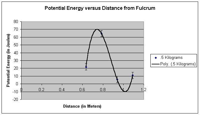
With our background knowledge of closely related topics, we theorize that there is a definite point where a weight flies the highest when a fulcrum is shifted along the base of a catapult. As the fulcrum is shifted left and right, when the missile is .7 m from the fulcrum, it will fly the highest and therefore exert the highest potential energy.
Preparations Before
Experiment:
Back
to top| Equipment for weight| Steps
to Make Weight| Final Weight| Lumber
Needed| Creating Plank| Creating
Box| Final Box and Plank|
Equipment Needed for
Preparing 100 lbs. Weight:
Back
to top| Back to Preparation
·
15
in tall paint container
·
100
lbs. of concrete
·
Hook
·
8
ft long rope
Steps to Make
Weight: Back
to top| Back to Preparation
1.
Pour
concrete mixture into paint container
2.
Prepare
concrete as directed on the bag and place the hook in the center
3.
Let
the concrete set and once solid tie the rope to the hook
The Final Product should look like this: Back to top| Back to Preparation

· One 2 x 2 in. board that is 10 ft. long
· One 2 x 10 in. board that is 12 ft. long
· One 2 x 4 in. board that is 10 ft. long
Steps to Create the Plank: Back to
top| Back to Preparation
1. Saw the 2 x 2 in. board into 10 in. segments (you will need 8 of these segments)
2. Saw 5ft. (60in.) from the 2 x 10 in. board
3. Place the eight 2 x 2 in. segments 6 inches apart from each other, on the cut 2 x 10 in. board and drill into place (see figure below)

Steps to Create the Box: Back to top|
Back to Preparation
1. Saw the 2 x 4 in. board into segments that are 20 in. long (you will use only five of them)
2. At a 45 degree angle saw the rest of the 2 x 10 in. board into trapezoidal segments that are 20 in. long ( there should be four) (See side view of figure below)

3. Assemble the four 2 x 10 in. segments together to form a box and drill into place
(see birds eye view of figure below)

4. Place the five 2 x 4 in. segments across the top of the box and drill into place
Final Product:
Back
to top| Back to Preparation

Experiment:
Back
to top| Equipment| Procedure|
Equipment needed for
experiment:
Back
to top| Back to Experiment
·
Timer
·
Box
(used as fulcrum)
·
Plank
·
100
lbs. weight
·
Various
small weights to be launched (We used a: 1.5 kg weight, 2 kg weight, 1.1 kg
weight, 1 kg weight, 5 kg weight)
Procedure: Back to top| Back to Experiment
1. Set the box underneath a place where a hundred pound weight can be dropped
2. Set the first groove of plank on the box
3. Place the weight that is to be your projectile on the end of the plank furthest from the box
4. Hoist the 100 lbs. weight up in the air 2.5 meters above the box
5. Hold the weight up with an attached rope strung over the top of a pole (becomes like a pulley)
6. Let go of the rope allowing the massive weight drop on the top of the plank, projecting the small projectile weight into the air
7. Time the duration of the projectile’s motion8. Repeat steps 3-7 four more times with the same projectile, sliding the plank over to the next groove each time
9. Repeat steps 3-7 for each of the projectile weights

Data:
Back
to top|
Raw Data:
Back
to top
|
Time (in seconds) from Each of the Fulcrum Positions |
|||
|
Weight |
2 |
3 |
4 |
5 |
|
.5 |
1.35 |
.98 |
3.28 |
1.91 |
|
1 |
1.38 |
.78 |
2.16 |
2.66 |
|
1.1 |
.91 |
1.69 |
2.25 |
.59 |
|
1.5 |
1.20 |
1.55 |
2.06 |
1.78 |
|
2 |
1.34 |
1.50 |
1.22 |
2.04 |
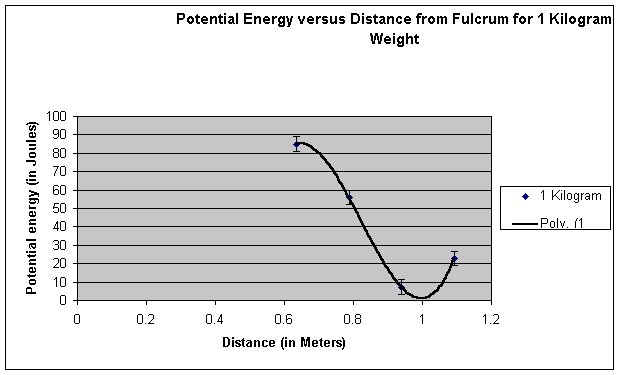
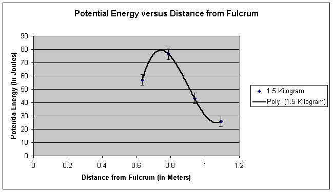
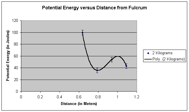
Graphs of Data: Back to top


Link to data file: Text | Excel
Conclusion:
Back
to top
After analyzing our data and creating our graphs, we concluded that there is in fact a definite point where a weight flies the highest when the fulcrum is shifted along the base of the catapult. We measured this point on the catapult to be approximately .75 meters from the fulcrum. This calculated amount can be recognized through our graphs and data table. In most of the graphs, the maximum heights occurred between .7 and .8 meters. We measured the potential energy to be 66 Joules at .78 meters from the fulcrum and only 37 joules at the second highest point, .9 meters from the fulcrum. This point was about .2 meters from the middle of the plank. We proved our hypothesis correct because not only did we find that their was in fact a definite point on the catapult where the object flies the highest, we found that this point is about .75 meters from the fulcrum, which is close to our theorized .7 meters. Our findings make sense because the larger radius would have to go faster in order to keep up with the smaller radius. Also, the spot would have to be near the middle as well because a slight counterbalance is necessary to insure optimal energy transfer.
Although we seem to have
found our answer to our problem, there is one factor that still does not add up.
The information we found from the graphs of the one and two kilogram weights
doesn’t fit the rest of our data. In these graphs there was a third order
polynomial, this is rather strange because it seems like the graph should
regress very slowly, ending at zero. The reasons we got these interesting
graphs could be a result of any number of factors including how squarely the
bucket hit the plank, the box’s destruction quotient, or how much it had been
destroyed. We attempted to raise the bucket to the same level in every
instance, but this was difficult and we may have been off by up to .25 meters.
These factors would have caused the discrepancy in the data, and the problems
we faced while performing our experiment. Although these problems did occur
there are ways that may have prevented them from occurring: if we had had a
true pulley instead of a rusty pole to hoist the weight up; had built the
fulcrum, box and plank out of metal and greased them up; had a winch that could
give us exact differences instead of eyeballing it and hoisting with my body;
and if we had more exact weights to drop and launch.
If I had the chance to
perform this experiment again, I would definitely lubricate the fulcrum and
build one that could withstand the pressure of 50 kilograms of dead weight on
top of it. I would also make the bar on the top narrower, allowing more data
points to be collected. Another possible change would be using a design more
similar to a trebuchet. With this apparatus, we would be able to make the calculations
more exact and incorporate some rotational mechanics.
Works Cited
1.
Author
Unknown. Home page. 28, October 2002 <http://www.physics.ohio-state.edu/~dvandom/edu/newcor.html
2.
Smith,
R.C. Mechanics. John Wiley and
Sons, Inc. New York, NY 1935.
3.
Huetinck,
Linda. Cliff’s Quick Review: Physics. Cliff’s Notes, Inc. New York, NY
4.
Gardener,
Robert. Famous experiments you can
do. USA, 1991
5.
Beiser,
Arthur. Physics. Addison-Wiesley Publishing Company,
Inc. USA, 1991