Fluid Dynamics in Microgravity .:. Go Up
Science | Drawings | Materials | Chemicals | Fasteners | Fluids | Survival | Mass | Procedure
Nick Young
Naomi Todd
Kevin Shump
Stephen Newberry
Joseph Intile
J. Michael
Harrison
Dan Bachhuber
Chris Murray – Advisor
2. Science .:. Top
Capillarity in microgravity is a well-researched field. A particularly comprehensive paper was published by Stange et al from ZARM (Stange, M., Dreyer, M. E., & Rath H. J. (2003). Capillary driven flow in circular cylindrical tubes. Physics of Fluids. 15(9) 2587-2601). They researched the effect of tube diameters, with different fluids on the rate of fluid rise in the tubes. In this study, we intend to look at a number of aspects of fluid flow that we have not seen in the literature. We intend to look at the effect of restrictions in a capillary tube, tapering of the tube, and we will try to manipulate a droplet after it has exited the tube.
It is our hypothesis that by changing the shape of the tube the fluid will behave differently due to the alterations (tapered end, restriction within the tube, and collision path) that will affect the characteristics of the liquid itself.
We will construct a Plexiglas container that will hold three partially immersed capillary tubes in separate chambers. We will use the provided video camera and a backlight inside the experiment apparatus to view the results of our experiment. The fluid will be dyed to enhance visibility. We will have a ruler or other form of measuring device that will be used to calculate actual dimensions from the video. We will construct the apparatus to have three small chambers in which different experiments can be performed. We intend to use silicone fluid in small amounts in each chamber.
3. Drawing – Description of apparatus .:. Top
The apparatus is very similar to the one our DIME team used last year, except that the inner box will contain three separate cells each designed to hold only about 50 cc of silicone fluid. The cells will be made from .375“ solvent welded polycarbonate plastic. This type of plastic gives the boxes greater drilling and impact resistance. The bottom plate of the outer cell will extend a little to the front and back creating a flange that can be drilled to allow the passage of the bolts that mount it to the mounting plate. Each box will have a lid held tightly shut by several screws that penetrate the lid, and engage the side walls of the cell. Where a lid contacts the top of its cell, there will be a closed cell foam gasket to seal the contents within. These gaskets will be glued to the lid and further secured by the screws. There is a 1/2” gap between the two cells that will be strategically cushioned with closed cell foam material. (A 1/2” Ensolite sleeping pad or similar). The experiments will be mounted to small slabs of polycarbonate plastic (tube mounting plates) that will hold the experiment for a particular cell in place once the top is screwed down. These will be above the pinning edge so that the silicone fluid will not rise up behind the plates. The surface above the pinning edge in each cell will be coated with Teflon to further prevent migration of the silicone fluid.
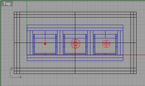
Top View .:. Top
The gap between inner and outer cell has closed-cell foam to position the cell and absorb some shock. In this view you cannot yet see the mounting flange as we haven’t rendered it yet, but we know that it mustn’t cover the corner holes on the aluminum mounting plate, and that the cells must be within view of the camera. In the inner cell you can see the tube mounting plates from the top, and the capillary tubes being held by the tube mounting plates.
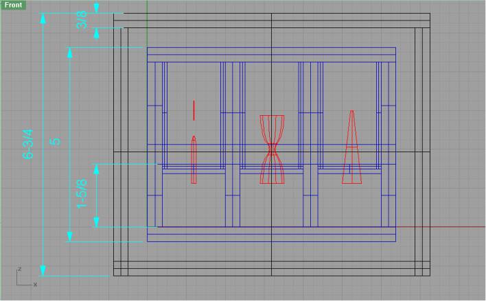
Front View .:. Top
This is the side that the camera sees. Note that you see the tube mounting plates front-on here. The mounting plates are removable by sliding them upwards out of a groove in the back of each cell. At fluid level in the each cell there is a step decrease in the wall thickness. The cell walls above this point will be coated with polytetrafluoroethylene (ptfe). The geometry of this will provide a pinning edge to prevent the fluid from climbing further up the walls of the cells – the ptfe coating will aid as well. Around the capillary tubes there will also be a ptfe wetting barrier. As we refine our analysis, we will need to revise some of these dimensions – especially the height.
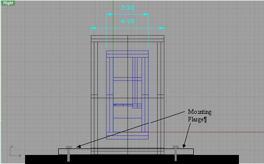
Side View .:. Top
In this view you can see how the tube mounting plates slide into a groove in the back of each cell. The tube mounting plates will be held in position by the lid when it is fastened down. You can also see how the mounting flange will be bolted to the mounting plate.
4. Materials .:. Top
Here is a table
of the materials we will use.
|
Tuhs DIME
materials |
||
|
|
|
|
|
|
|
|
|
|
Material |
|
|
Plastic |
Polycarbonate |
|
|
Silicone
fluid |
Dow
200(R) .65 CST |
|
|
Oil Red O
Dye |
C26H24N4O |
|
|
Closed
Cell Foam |
Polyurethane |
|
|
Elastic
Shock Cord |
Nylon/Neoprene |
|
|
Wetting
Barrier/Coating |
Teflon |
|
|
|
|
|
|
|
|
|
|
Fasteners: |
|
|
|
Bolts
.25", 5/8" |
steel |
|
|
Capillary
tubes |
Acrylic |
|
|
Lid
Screws |
steel |
|
|
|
|
|
|
Mounting
Plate |
Aluminum |
|
5. Hazardous Chemicals
.:. Top
The
only somewhat controversial material that we use is the Dow Corning 200(R)
Fluid, .65 CST (Hexamethyldisiloxane).
It is an inflammable liquid, and is somewhat volatile, so we will need
to be careful with it. The MSDS
(Included here) says that it is not particularly toxic, but it should be used
in a well ventilated area, so we will need to use the fume hood, as well as
wear gloves. It looks like the real
danger is the inflammable nature of the liquid – it will be important to keep all
possible sources of ignition away from the silicone fluid. I have included the MSDS of this
substance. Since we plan to use around
50 cc of this liquid per cell, we think we will be safe. An issue that occurs to us is that the
silicone fluid will need to be shipped to GRC directly, as we cannot take it
aboard the plane.
The dye we will use is Oil Red O – apparently it not considered hazardous according to the MSDS. (Also Included)
6. Fasteners .:. Top
Since
our inner and outer cells will be solvent welded together, the only fasteners
we will use are the ones that mount the outer cell to the mounting plate, and
the screws that hold the lids on.
The steel bolts to the mounting plate will be 1/4” width, and 3/4” long with a 20 thread on them. This will allow them to penetrate the .375” mounting flange on the front and back of the outer cell, and engage the threads of the aluminum mounting plate by at least 3/8”. We will use washers to spread out the force of the bolts to avoid cracking our base plate
The mounting flange will bolt to the mounting plate
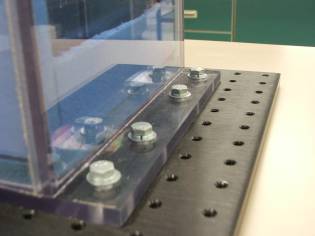
We will use the same type of screws the DIME team used last year to fasten the lid. (#8-32 x 1”) The hole in the cell wall will be tapped out to receive the threads of the screw so that it can be tightened. This worked well last year.
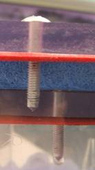
Close up showing lid screw and gasket concept
7. Fluids .:. Top
We
will have a double-celled apparatus with both the inner and outer cells clamped
shut and sealed with gaskets. The lid
of both cells will have a closed cell foam gasket where it contacts the lid,
and on each side there will be two screws that will be tightened so that the
gasket is compressed. Since the lids
are transparent, one can visually confirm that the gaskets are compressed by
their change of appearance. The
pre-wetting of the capillary tubes will happen in a separate container in a
fume hood using gloves.
8. Survival .:. Top
On this experiment to create an isolated droplet in zero gravity, this team has designed numerous safety features to ensure survival of the apparatus. These features include two layers of polycarbonate, closed-cell foam, fasteners, and gaskets around the edges. In properly constructing these safety features, it will allow for the apparatus to be repeatedly used for testing.
There will be two layers of polycarbonate, one protecting the innermost contents, and the other around the inner cell, insuring no leaks and minimizing damage. The use of polycarbonate is to ensure that the apparatus is adequately protected from the fall and subsequent capture. The inner layer will protect the actual experiment. The outer layer will create another safety barrier, for both the NASA equipment, and for keeping the silicon fluid in its desired location. It is of utmost importance for this team to keep the silicon fluid in the inner container.
The gaskets will be the same as we used last year. They were successful in preventing any leaks whatsoever using much greater volumes of liquid than we plan to use.
The last safety feature that will be discussed are the closed-cell foam which will be placed between the two layers of our double containment. The foam will cushion and position the cells.
This team feels that in using these safety features, our apparatus will be secure and be able to survive the impact of the 2.2-second drop.
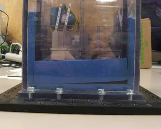
Closed cell foam to cushion the inner cells
9. Mass .:. Top
|
Tuhs DIME
materials and mass |
|
|
|
||
|
|
|
|
|
|
|
|
|
|
|
|
|
|
|
|
Material |
Density
(kg/m3) |
Volume
(m3) |
Mass (kg) |
|
|
Plastic |
Polycarbonate |
1200 |
2.023E-03 |
2.428 |
|
|
Silicone
Fluid |
200(R)
Fluid, .65 CST |
761 |
1.5000E-04 |
0.114 |
|
|
Oil Red O
Dye |
C26H24N4O |
|
|
0.010 |
|
|
Closed
Cell Foam |
Polyurethane |
58 |
2.017E-03 |
0.117 |
|
|
Elastic
Shock Cord |
Nylon/Neoprene |
1219 |
4.826E-06 |
0.006 |
|
|
Wetting
Barrier/Coating |
Teflon |
|
|
0.050 |
|
|
|
|
|
Total |
3.409 |
|
|
|
|
|
|
|
|
|
Fasteners: |
|
qty |
mass (kg) |
total
mass (kg) |
|
|
Bolts
.25", 5/8" |
steel |
8 |
1.000E-02 |
0.080 |
|
|
Capillary
tubes |
Acrylic |
3 |
2.500E-02 |
0.075 |
|
|
Lid
Screws |
steel |
16 |
5.000E-03 |
0.080 |
|
|
|
|
|
|
|
|
|
Mounting
Plate |
Aluminum |
|
|
3.084 |
|
|
|
|
|
|
|
|
|
|
|
|
|
Kg |
lbs |
|
|
|
|
Our Mass |
6.728 |
14.82 |
|
|
|
|
Limit of
Mass |
11.340 |
25 |
10. Procedure .:. Top
- The tube mounting plates will be removed from the each cell in order to access them.
- The capillary tubes will be wetted with the silicon fluid in a separate basin.
- The inner cells will be filled to the desired depth with the experimental fluid in a fume hood.
- Students will ensure that there is adequate ventilation.
- Students will wear gloves to protect from chemical exposure.
- The tube mounting plates will then be placed back into the cells so that the tubes are immersed to the desired depth in the silicon fluid.
- The inner cell lid will then be screwed securely in place and be placed into the outer cell. A visual inspection of the gasket should show compression.
- The outer cell lid will also then be screwed shut.
- The experiment will be attached to the experimental rig so that it is in view of the camera.
- The backlight will be turned on.
- The camera will be checked to make sure that it is recording and that the tubes are in the view of the camera. Focus and Zoom will be checked at this time as well.
- One final check will be made in order to confirm that the dropping apparatus will be functional during the drop.
- Ensure that the tubes are correctly positioned
- Ensure that the camera is recording
- Ensure that the lids are securely fastened
- Retrieve the video information from the educational rig’s on-board camera, and make at least one redundant copy of it.
11. Electrical Diagram
There are no electrical connections with our apparatus.
12. Time Delay
We will not use the time delay feature.
13. Data Logger .:. Top
We will not use the electronic data logger. We will be using the built in camera that comes with the educational rig. The materials we will be using will be transparent both in front and behind the capillary tubes to allow the backlight to illuminate, and the camera to film the experiment. We will put a dye in the silicone fluid to enhance its visibility, and have designed the apparatus so that the capillary tubes will be within the viewing angle of the camera.