The Cloud Chamber of Secrets: The Effect of Magnetic Fields on Radioactive Particle Velocities in a Cloud Chamber
By Roberta Gannett, Cassie Miura, and Allison Nishitani
Background: A cloud chamber is an apparatus that tracks radioactive particle’s paths. It works by cooling isopropyl alcohol vapor at the bottom of the chamber with dry ice, while the top of the chamber is at room temperature, which causes the vapor to rain down. The vapor is super-cooled, meaning that it is in a vapor form at a temperature that is below where vapor can normally exist. Because of this, the vapor will easily condense into a liquid. An electrical charge that passes through the chamber ionizes the vapor, which leaves positively charged atoms. The ionized atoms attract other atoms to begin condensation.
The cloud chamber was first developed by physicist C.T.R Wilson in 1911. His experimentation originated from these main principles:
· Clouds form on dust-This knowledge was gathered by John Aitken. This experiment involved a simple glass jar and water. His purpose was to observe the air as it became saturated with water molecules.
· Expansion and cooling-When air is held within container it causes an increase in volume and a decrease in air pressure. When this is accompanied by a decrease in temperature, water vapor condenses on the dust in the air, producing a cloud.
· X-rays produce nuclei-Wilson expanded upon Aitken’s experiment by hypothesizing that water could condense not only on dust but also on ions. To do this Wilson exposed the air in the cloud chamber to x-rays. He then put an electric field around the cloud chamber to show that the nuclei were changed (Cambridge).
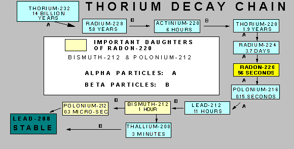
The source used in the experiment is Thorium-232, in the form of a Coleman lantern mantel. Thorium is a naturally occurring radioactive element, that has twenty-six known isotopes (though twelve have half lives of less than one second). Thorium-232 undergoes natural disintegration and eventually is converted through a ten-step chain of isotopes to lead-208, a stable isotope; alpha and beta particles are emitted during this decay. One intermediate product is the gas radon-220, also called thorium emanation or Thoron.
Statement of the Problem: The purpose of this investigation is to successfully construct a functional cloud chamber to observe how the radius of curvature, and thus the velocity, of a radioactive particle varies as the magnetic field is manipulated within the chamber. The independent variable is the strength of the magnetic filed, which will change the dependent variable, the velocity of the alpha particles.
Hypothesis:
If the magnetic field in
a cloud chamber increases, then the radius of curvature, and thus the velocity
of the particles, will also increase.
• Plastic airtight chamber
• Sponge
• Black paint
• Rubber bands
• Hot glue
• Sheet metal
• Putty
• Radioactive source (Coleman lantern mantle)
• Isopropyl alcohol
• Dry ice
• Gloves
• Cooler
• Ice pick
• Ice tray
• Slide projector
• Digital camera
• Digital video camera with tripod
• TV
• VCR
• Dry erase marker
• Ruler
• Strong magnet (neodymium)
• Hall Effect probe
- Cut the bottom out of the container
- Paint the metal plate black
- Secure a metal plate with putty as the new base
- Remove the clamps from the lid
- Create a very thick hot glue barrier along the inner top part of the chamber (not the lid)
- Cut sponge into long strips about 1 cm tall
- Glue the sponge to the glue barrier
• Level surface that is resistant to cold temperature
• Access to sink and soap
• Dark room
• Constant temperature
• Room for all lab associates
- While wearing gloves, crush the ice and level it in the ice tray
- Wet the sponges with the alcohol
- Place the radioactive source in the chamber
- Place the magnet under the chamber and record its position
- Secure the chamber lid with rubber bands
- Place the chamber on the ice
- Turn on and adjust the light source
- Turn off other lights
- Film for 15 minutes
- Repeat at least 12 times
- Find the best footage from the 3+ hours of video
- Mark magnet location on TV screen
- View chosen footage on TV in slow motion
- When a curved particle track appears, pause the video and complete the circle with the pen
- Measure the radius and the distance to the magnet from the center of the circle
- Convert the measurements from the TV into meters and find the real lengths by using the proportion from the diameter of the chamber on the TV and the diameter of the real chamber
- Use the Hall Effect probe to measure the magnetic field produced by the magnet on the bottom of the chamber at intervals of .5 cm
- Find a regression formula to calculate the magnetic field at any distance
- Calculate the velocity by using v=rqB/m
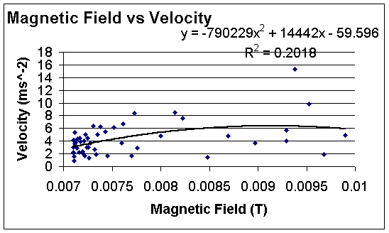
Conclusion:
The
results from the investigation are inconclusive.
There is a definite increase in the radius of curvature in terms of the
presence of a magnetic field; however, we were unable to draw a strong
conclusion as to whether a stronger magnetic field strength creates a greater
radius of curvature (though our line of best fit did indicate an upward
trend). One of the main reasons
for these results is a large margin of error which will be discussed in the
next section.
Error
and improvements: The
detail of our experiment and the sensitive nature of the cloud chamber
apparatus accounts for multiple sources of possible error. First, there are
the inherent limitations of our materials and tools. Through the process of
building the actual chamber, we experimented with several different shapes and
materials. The chamber we decided to use in the experiment lent itself to easy
data collection, and was the best environment to house the cloud, but still
had some problems. Since the chamber is made out of plastic, the isopropyl
alcohol, in the form of vapor and in the liquid form in the sponge, had the
tendency to cause the plastic lid to crack. In an effort to reduce breakage,
we made a protective glue barrier for the sponge and did not use the clasp
built on the chamber, but instead used rubber bands to secure the lid. The
idea was to reduce the alcohol’s contact with the plastic surface and to
reduce pressure on the lid. The drawback was that the chamber was no longer
airtight. Another problem was that the plastic slightly distorted our ability
to view cloud activity and reflected light, making it difficult to both view
and film. We wanted the bottom of the chamber to be as cool as possible, so we
cut out the plastic bottom and replaced it with black sheet metal. This did
make the chamber more active, but the metal also collected condensation, which
can easily disguise trails and the cloud itself. Some suggestions to improve
the chamber are to get a glass container and have the bottom professionally
cut out and replaced with sheet metal. Then, use some sort of absorbent black
fabric to cover the bottom (note: although recommended, velvet does not work
because it collects lint and still shows condensation). The glass container
must be clear, high quality glass (low quality glass severely distorts image),
and preferably square to reduce distortion. Some other problems with tools and
materials included our ability to control the spread, focus, and intensity of
our light source, a projector. We tried various flashlights and found that
those were no better, but lighting should not be a problem if the chamber is
square instead of round. Another source of error was the ice. In order for the
chamber to work, the bottom, which sits on top of the ice, needs to be level.
We tried leveling the ice, specifically buying relatively flat blocks of ice,
and melting it with a hot pan, but it was still difficult to keep level.
Melting the ice with a pan worked well, but since the ice does not last very
long, and the procedure takes a long time, it seemed to be defeating. Ideally,
ice could be requested in a rectangular and uniform size. Error with the
source included the metal base that was attracted to the magnet and both its
size and relative position, which obstructed the camera view. If one could
safely handle the source, it would be helpful to either make a plastic base,
or find some other material like string to suspend it from the top. For
viewing purposes, it would be good to decrease the size of the source, but
that would also decrease its strength, which would probably be more harmful to
the experiment. Our magnet had sufficient strength, but since the bottom of
the chamber was metal, it was difficult to position and not visible on camera
screen. Also, the poles of the magnet were unknown. To amend these flaws, one
could purchase a magnet with known poles, and specifically mark the target
position on both the top and bottom side of the metal sheet (chamber bottom).
The
largest amount of error in the experiment can most likely be attributed to
error in the data collection process. This largely involved the camera we
used. In order to measure the radius of curvature, we had to be able to
accurately pause the camera. This capability was inaccurate because of human
error pushing the button, but also because of the relatively few frames per
second of which the camera was capable. Also, since the camera was positioned
above the chamber, it had tendency to focus on the lid, rather than the bottom
where the trails appeared. The obvious fix for the inaccuracies is to use a
camera that is more technologically advanced. A digital video camera would be
ideal because the footage can be broken down by individual frames, and could
also be uploaded to a program that could digitally emplace a grid over the
entire picture. Since we did not have these capabilities, we were forced to
use the T.V. screen and a dry erase pen to gather our measurements. We then
had to account for the larger viewing picture by making our measurements
proportionate to the actual size of the chamber. Our ruler could not be
perfectly accurate and did not contour with the curve of the screen.
Possibly the worst problem with the data collection process was that
because we had to draw on a T.V. screen, we were not able to use a compass to
draw in the rest of the particle track so that we could measure the radius of
curvature. The pencil lead in a
compass would scratch the screen, so we had to use a dry erase marker instead
and complete the circles by hand. We
tried to control the immense amount of error in this process by having the
same person draw all the circles and by checking the circle’s roundness by
measuring the diameter in several directions, but no matter what, hand drawn
circles are a terrible substitute for perfect compass produced ones.
Also, the pen we used was thick, and could smear and rub off. Like the
chamber, we could not see the magnet in the video and had to estimate its
actual position. These errors could also be significantly reduced with the use
of a more sophisticated camera and computer program. The final source of error
is the Hall Effect probe used to measure the magnetic field in the chamber.
When we measured, the magnet was not in the exact position it was during the
experiment, the probe was large so it was hard to take readings at small
intervals, and the reading was constantly changing. We should have had a fixed
place for the magnet, but the other errors are difficult to amend. One could
use a smaller and more sophisticated probe, but that was not practical in our
case.
Cambridge Physics. “Cloud Chambers.” Accessed: 10/26/03. <http://www.phy.cam.ac.uk/camphy/cloudchamber/cloudchamber_index.htm>
Carusella, Brian. “Cloud Chambers.” Last Updated: 8/18/98. Accessed: 10/26/03. <http://home.houston.rr.com/molerat/cloud.htm>
Bock, Rudolf. “Cloud Chamber.” Last Updated: 4/9/98. Accessed: 10/26/03. <http://rkb.home.cern.ch.ch/rkb/PH14pp/node29.html>
Foland, Andrew. “How to Build a Cloud Chamber.” Accessed: 10/26/03. <http://www.lns.cornell.edu/~adf4/cloud.html>
McNab, Andrew. “The Cloud Chamber.” Last Updated: 2/2/97. Accessed: 10/26/03. <http://www.hep.man.ac.uk/u/mcnab/cloud/>
http://www.phy.cam.ac.uk/camphy/cloudchamber/cloudchamber_index.htm
A good site with clear explanations of the theoretical propositions concerning cloud chambers. Interactive animations serve as a good visual aids.
http://home.houston.rr.com/molerat/cloud.htm
A clear explanation of how a cloud chamber works and a fair explanation of how to make your own chamber.
http://www.lns.cornell.edu/~adf4/cloud.html
An alternate chamber model that might work better for you.
http://sargentwelch.com/category.asp?c=27720&sid=GOOGLE&eid=GL074
Academic resources...if you get desperate you can buy a cloud chamber.
http://www.lateralscience.co.uk/cloud/
Good illustrations of the original cloud chamber.