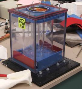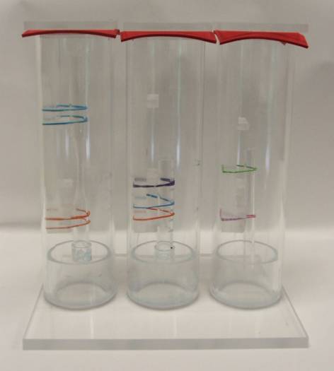
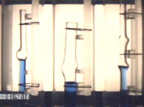
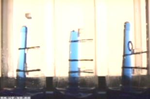
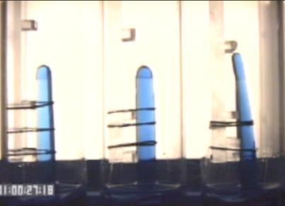
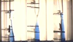
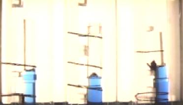
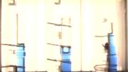
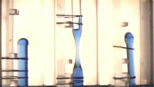
Picture of the three cells holding three experiments.
|
Nick Young Tualatin High School |
Chris Murray
(Instructor) |
Introduction
| Method | Results | Conclusion
| Bibliography | Links | Photos
Drops 1-3 Video ( 92 Mb Quicktime) |
Drops
4-11 Video ( 330 Mb Quicktime)
Drops 1-3 Video (YouTube) |
Drops 4-11 Video (YouTube)
Drop Data (Excel)
A common area of study in microgravity deals with unhindered capillarity. In the presence of gravity, fluid in a tube will rise to a specific height based on the contact angle, surface tension, and diameter of apparatus (Giancoli 1998, p. 296.). In microgravity, capillary tubes can be used to pump liquids the entire length of the tube (Stange, et al. 2003, Siegel 1961, NASA CAPL-2, 2004, ZARM 2004). In April of 2005 (Tualatin High School Physics, 2005), a group of students used capillarity with water to eject droplets into the air with limited results due to the wetting characteristics of water and glass. Therefore, we intend to use silicone fluids and small geometries to obtain more consistent results. We propose to use this capillarity to investigate three different fluid experiments dealing with liquid dynamics in microgravity, related to creating droplets in microgravity. The two experiments will deal with tubes that are tapered to varying degrees, and capillary flow through an hourglass shaped tube and through tubes of differing diameters.
With the tubes with different diameter exit openings, we hypothesize that only the smaller openings will actually eject the droplets, and the larger openings will not have sufficient momentum to overcome the surface tension and adhesion with the tube.
Regarding a restricted tube, like the hourglass shape, we are expecting the velocity of the liquid to increase as it approaches the point of restriction. At the point of greatest restriction, we hypothesize that the velocity will be great enough to propel a droplet into the air within the tube above the constriction.
Method .:. Top
Picture of the three cells holding three
experiments.
|
|
|
The cells were filled with 50 ml of DOW 200 .65 cSt fluid with a blue dye added and filmed with a 640x480 30 frames per second video camera against a backlight. The whole apparatus was dropped in the NASA Glenn Research Center 2.2 drop tower. We then analyzed the height of the fluid frame by frame from the video.
|
|
|
General:
We analyzed the fluid height by using video analysis software. The scaling of the tubes was based on the width of the whole assembly being 188 mm. All time is in seconds, all heights are in mm. Due to the position of the backlight, the first 1.3 cm of rise in the tubes is not visible against the backlight, so for all graphs, the data starts from the first frame that is above this line. The height was taken from the center of the tube.
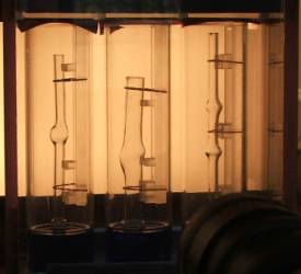
Drop 1: Tubes with bulges .:. Results
Left: 6 mm tube with one bulge in the middle. The fluid rose up around the side and almost created an air bubble but the tube was to large so the fluid just leveled out before The fluid rose much higher on the right side than the left after it passed the bulge, but that can be attributed to the fact that the bulge is not a perfect circle.
Middle: 13 mm tube with a not as drastic bulge. The fluid rose up the right side of the bulge and after it passed the bulge leveled out.
Right: 6 mm tube with two bulges. As the fluid passed by the first bulge it created an air bubble that lasted until it came to the top at the second bulge, and it looked like it may have created a second air bubble had there been time.
Drop 2: Fan sprays and large taper tube .:. Results
Left: Medium size tapered tube. When the fluid passed above the lip of the tube it wasn’t small enough to create a droplet and instead the fluid wetted the lip of the tube and began crawling down the tube.
Middle: Large size tube with a slit in the tube. It created a very small droplet on the right side of the tube looking in.
Right: Large size tube slightly tapered. This one also had too large of an opening to create a droplet, and it wetted the upper lip and began to crawl back down the tube.
Drop 3 .:. Results
Unleash the crane before dropping the experiment. It works better that way. (We forgot to )
Drop 3B
Tube 1: Large tapered tube with a medium sized opening. (9 mm tapered to 7.6 mm)The same thing happened as in the third tube in drop 2.
Tube 2: Large slightly less tapered tube with a medium sized opening. (9 mm tapered to 7.1 mm) The tube was attached to the backing and the fluid, after spurting out and looking like it would do the same thing as tube one, wetted the backing and fluid crawled all over the backing.
Tube 3: A 9 mm tube tapered to 6.5 mm. The fluid spectacularly overran the end of the tube, but was pulled down by the surface tension and the adhesion with the tube.
Drop 4 .:. Results
Left: Medium size tube tapered to be quite small. (9 mm tapered to 4.3 mm) There seems to be a small air bubble just as the fluid approaches the tapered part. Because of this, the fluid spits out two bubbles right away. The rest of the fluid doesn’t have enough momentum to form a droplet so it wets the rim and rides back down the tube until the end.
Middle: 9 mm tube tapered to 5.4 mm. It ejects a stream right away but then the stream turns into 3 droplets and starts to go back down (the last droplet looks like it might be caught by the tube on the way back down) but it doesn’t because the time is up.
Right: 9 mm tube tapered to 2 mm. Creates a stream that separates itself into about seven little droplets.
Drop 5 .:. Results
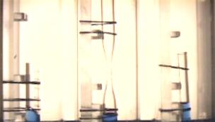
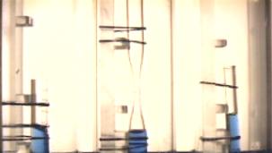
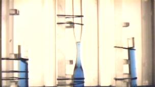
Left: 6 mm Hourglass As the fluid goes through the narrow part, the fluid climbs the sides very high and then evens out.
Middle: 9 mm hourglass tube more straight on the right side than on the left side. Before the fluid goes through the narrow part another little air bubble is there. This must be due to a mistake of some sort. When the fluid is going through the wider part of the tube it climbs really high on the right side.
Right: 13 mm hourglass tube with a fairly wide middle and an hourglass shape, of course. The fluid does nothing interesting until the fluid rises completely over the constriction in the tube and is back to the original width of the tube. Then the fluid rises up the sides of the tube but does not rise in the center. It rises higher on the left side, the side that the tube is less drastically bent on. From the data, the side that is less bent seems to encourage more climbing of the side of the tube. This could be because it takes less time for the fluid on the left side to rise because it has less space to cover because that side is flatter. Therefore the left side has more velocity perhaps and it goes ahead of the right side. After a little while, the fluid evens out.

Drop 6 .:. Results
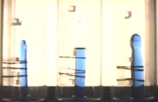
Left: (9 mm not tapered).
Middle: (9 mm tapered to 8.6 mm)
Right: (9 mm tapered to 8 mm) On all of these, the fluid shot out past the end of the tube, and was then hauled back to the tube by adhesion and surface tension. On being pulled back to the tube, they wetted the outside of the tube and began crawling down the outside of the tubes well before impact with the air bags. Notice on the graphs the inflection point between 0.5 and 1.0 seconds that shows when the fluid left the end of the tube and began to slow down. At the end of the graph you can see the fluid level go down – not due to impact with the airbags, but due to the fluid’s climbing down the outside of the tube.
Drop 7 .:. Results
Left: Medium size tube with a very small opening and another plain, unaltered medium size tube a small distance above the first tube. The water forms a stream that looks like it might form droplets like the other tubes with small openings, but it wets the tube above it instead and begins to crawl up the left side of the tube. The fluid that does not make it to the tube but is still attracted to its friends who are touching the upper tube gets pushed a little to the side and it begins to crawl down the left side of the tube.
Middle: Medium size tube with a smallish opening and a tube above it with a slightly smaller opening than the lower tube. Its hard to tell what happens, but there is a stream of fluid and it appears to go into the upper tube and spread out very thin, then the fluid appears to conglomerate at the bottom of the tube and just stay there. It seems like the fluid’s attraction to itself is stronger than its attraction to the tube when it gets thin enough.
Right: still medium size tube with a larger opening than the second and first tube, but with a tube above it that has a smaller opening but is closer to the lower tube than the other two are. A steady, thick stream of fluid goes into the upper tube and rests in the upper tube. It is interesting to notice that the fluid in the right tube settles at the lower end of the tube not due to gravity, but due to surface tension. (i.e. it is seeking to have the least exposed surface area.)
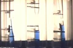
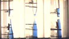
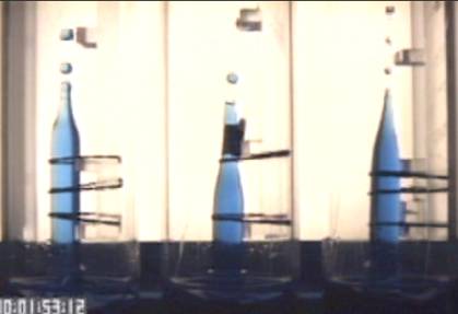
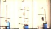
Time sequence showing drop transfer
Drop 8 and 9 (Same – 8 is with front lighting, 9 is with back lighting) .:. Results
Left: bubble gum tube. Fluid rises up and goes out the hole, but because the tube is stopped up and when the hole is also stopped up with fluid, the fluid cannot rise any farther because the air is keeping it down.
Middle: with the better light, it seems that the fluid in this got on the outside of the tube somehow, but that doesn’t explain why it stops after a certain point. But the fluid, though appearing to stop, does actually continue climbing very very slowly before it is stopped by the impact with the air bags. This indicates that the air was maybe escaping from the seal at the top.
Right: (6 mm straight tube – control) The control does the same thing that it appeared to do in the previous drop. Notice how uniform the rise is in the control tube as indicated by the graph below.
Drop 10 .:. Results
Left: This tube goes abruptly from 9 mm to 13 mm to 9 mm. This simulates the wetting barrier that we thought would prevent the fluid from going around the 90 degree turn. However, the fluid does go up it and then when it goes back into the smaller tube, almost creates a bubble. Apparently the wetting barrier can be overcome by momentum of the fluid.
Middle: 13mm to 9 mm to 13 mm. Inverted version of the first tube, and it creates almost a bubble at the top. Not in the frame below a small cone of fluid being formed as the channel narrows.
Right: A tower of tubes that are smaller and smaller (three different sizes). The fluid just goes up the tower like normal. The fluid was able to wet the bottoms of the tubes and climb right up.
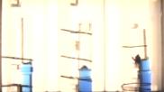
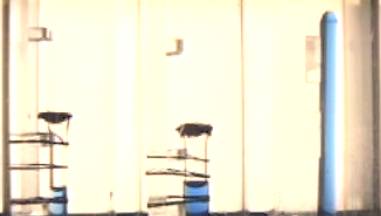
Time sequence showing the fluid negotiating changes in tube thickness
Drop 11 .:. Results
Tube 1: 9 mm with a bunch of slits in the right side of it. The fluid just rises at an angle going up the left side the highest. If you watch the video you can see the fluid climbing freely up the left side, and dragging it past the geometry of the right side.
Tube 2: Classic hourglass. (9mm) In this one we drilled a small hole at the constriction, thinking that maybe the pressure would drop below the outside pressure and entrain bubbles. This did not happen either because the velocity was not enough, or because the surface tension was too strong.
Tube 3: 9 mm tube with a hole drilled about halfway up. We wanted to see if the fluid would climb out the hole and climb up the inside and the outside. This did not happen.
Time sequence of drop 11
Our original hypothesis was originally designed to test three different experiments in microgravity: silicon fluid capillarity in a tapered tube, in a tube with a constriction, and splitting an isolated droplet once it has left a tube. Our actual experiments differed from these original plans. Ending up with more drop time than we had planned for, we were able to test a multitude of experiments, consisting of tapered tube capillarity, hourglass shape constrictions, launching droplets of fluid between tubes, and tubes with slits and holes. We never tried to split a droplet that had already exited a tube.
The basic purpose of our experiment, however, remained the same: to test the characteristics and properties of a more consistent liquid (silicon fluid) in various micro-gravity situations.
Our results were mostly in favor of our expectations as far as capillary action was concerned: the fluid in the tapered tubes rose faster than in the straight tubes, and even quicker in the constricted, hourglass shaped tubes. We hypothesized that in an hourglass shape that the fluid would perhaps make a droplet inside the tube, and although you can see it shoot up the side of the tubes after the constriction, the fluid remained in contact with the walls. We were even able to get an isolated droplet to be launched through a gap between one tube and another. Some of our other hypotheses concerned making bubbles within the tubes and raising the liquid past the slits in the side of the tubes. We were able on several accounts to see a bubble being formed within the tubes during the drops. In some of the drops, the tube’s opening at the top was so large the liquid was not able to get enough upwards velocity to separate from the tube at the opening. Rather the liquid would sort of blob up out of the tube in a thick stream while staying connected to the liquid still inside the tube, and then would begin to climb back down toward the tube before hitting the air bag at the bottom because of its adhesion with the outside of the tube. Watching the video, we could see the point at which the upward momentum of the rising fluid was arrested by adhesion and surface tension, and the entire thing started to come back down. At this point, the fluid would overcome the right angle geometry of the top of the tube and climb down the outside.
Our hypotheses were mostly correct: we succeeded in making isolated droplets and found that the liquid moved faster through the constrictions of an hourglass tube. We also did not expect the liquid to remain in a connected blob, and then climb down in the tubes with larger openings. In conclusion, the tests agreed with most of our hypotheses and ideas of capillarity, despite the few unexpected results.
Stange, M., Dreyer, M. E., & Rath H. J. (2003). Capillary driven flow in circular cylindrical tubes. Physics of Fluids. 15(9) 2587-2601
Siegel, R. (1961). Transient Capillary Rise in Reduced and Zero Gravity Fields. Journal of Appl. Mech. 83 165-170
Tualatin High School Physics Research (2005). Creating Isolated Droplets in Microgravity, Retrieved November 8, 2005 from
http://tuhsphysics.ttsd.k12.or.us/Research/DIME05/Final/index.htm
ZARM Center of Applied Space Technology and Microgravity. (2004). Capillary Rise in Tubes. Retrieved October 5, 2004, from
http://www.zarm.uni-bremen.de/2forschung/grenzph/isoterm/cap_rise/index.htm
NASA National Space and Aeronautics Administration. (1995). Capillary Pumped Loop-2 (CAPL-2). Retrieved October 7, 2004, from
http://ssppgse.gsfc.nasa.gov/hh/capl/capl.html
Physics – Principles with Applications. Giancoli, D. (1998). Physics – Principles with Applications. (5th ed.). New Jersey: Prentice Hall.
Links .:. Top
http://www.zarm.uni-bremen.de/2forschung/grenzph/ - Stange, Dreyer and Rath's site with videos from their paper. The data for our experiment design came from their work.
http://www.zarm.uni-bremen.de/ - The ZARM home page. ZARM is a major German microgravity research center.
http://exploration.grc.nasa.gov/DIME.html - The DIME homepage - explains the program in which we participated.
http://exploration.grc.nasa.gov/balloon/blob.htm - What happens when you pop a water balloon in zero gravity?
http://exploration.grc.nasa.gov/drop2/ - The homepage for the 2.2 second drop tower we used.
http://www.ncmr.org/research/drop51.html - The homepage for the 5.1 second drop tower that is at GRC.
http://www.nasa.gov/centers/glenn/home/index.html - The Glenn Research Center homepage - turn up your speakers!
http://www.nasa.gov/vision/earth/everydaylife/defy_gravity.html - NASA Amusement park science - great flash videos of free fall rides and why you experience zero gravity when falling