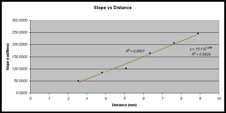
| If the magnetic field had directly
affected the eddy currents as of a linear
relationship it sort of could be
explained by the graph. The graph had
concluded a relationship of B to r of
about r^1.278 (green line, Graph 2.3),
which would comply only sort of with the
idea that a magnet’s power
proportionality decreases over the
difference if we take into account the
results from the first experiment. Since
the power to which r is taken according
to the first experiment decreases as we
get closer, it is possible that it
decreased to the point of 1.278, but not
certain. I would very much like to
reconcile this problem, and maybe find
the formula for decrease in power to
which r is taken over the distance for a
permanent magnet. Another problem is that
the graph of slope versus distance can
also be fairly accurately fit by a linear
equation (red line, Graph 2.3).
This would suggest not that the
relationship between magnetic field
strength and magnetic eddy current is
linear but that it is some negative root
proportionality such as r -(1/3),
or r –(1/2). Another
explanation is that maybe a more
dispersed magnetic field could cause a
higher eddy current than one less
dispersed. I based this on the fact that
it is harder to create a movement of
current to a place where charge
separation already is. In the eddy
currents case this would mean that with
magnets closer it would be a little
harder to produce eddy currents and with
magnets farther, a little easier.
However, this doesn’t make too much
sense considering the speed of
electricity. This entire problem,
however, may just be attributed to human
error. There were many places for human
error to be involved. For example, when
timing the weight’s speed error came
into play. This margin of error was about
± 0.2 rad/s
in each of the final results. Also, there
was uncertainty of ±
0.0035 Nm about my answer for frictional
torque. I also had many problems trying
to get the magnets at just the right
distances. This is seen in the Graph
2.3 by the distance of 5.06 mm, which
from the line of best fit seems to
suggest the magnet was actually at a
separation of 4.5 mm. I noticed,
furthermore, that the plate wobbled a bit
and was not precisely centered.
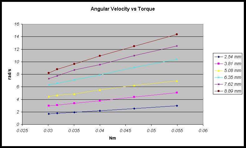
Overall, I was only really certain
that the relationship between eddy
current torque and angular velocity was a
linear relationship and a little less
convinced of the linear relationship
between magnetic field and eddy current
torque. Also, I was very much swayed
about the relationship in between
magnetic field and distance being linear.
I now see this relationship as a
regressing power function, contrary to my
hypothesis. A useful test to conclude
other answers would be a better method to
measure the B-field versus distance,
maybe one using a Hall-effect probe.
Another useful experiment would be one
where I both spread out small, eddy
producing magnets, and then compacted
them to see if dispersion really is a
factor.
|
Previous____Next