I.B.
Physics Research Project
Hovercraft: The Myth, The Legend, The Science
Chris
Kapfer
Andrew Kraushaar
Table of
Contents
Introduction: The History of Hovercraft ** Hypothesis ** The Hovercraft
Production
Lessons Learned and
Solutions ** Air
Pressure ** Data: The Good Stuff ** Interpretation:
Conclusion ** Wrap Up ** Bibliography ** Return
to Research Page
The History of the Hovercraft
As
modes of transportation have evolved, finding more efficient and economical ways
of movement have been the chief goals of developers. It is no wonder that from this evolution the hovercraft
arose. Making it a truly unique
vehicle, the hovercraft flies or “hovers” just a few inches off the ground on a
cushion of air (Chalin 378). This
feature lets the hovercraft maintain the identity of being a free roaming
vehicle, not confined by roads or water.
Yes, the hovercraft is amphibious as it can travel over most smooth
surfaces including ice, dirt, snow, water, and asphalt (Goldstein).
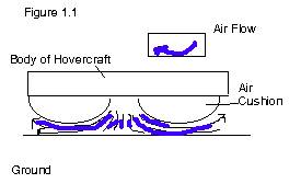
The
basic concept that fuels the design and creation of the hovercraft relies on
inflating a cushion of air. However, to
create the hovering phenomena the air flows around the bottom of the cushion as
seen in Figure 1.1.
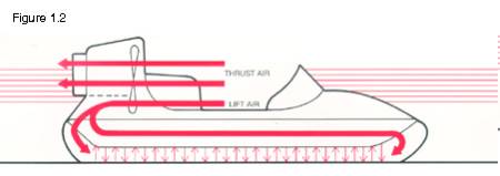
Hovercrafts have not experienced the popularity of cars, boats or planes, but nevertheless the production of the vehicle is continuously increasing as more and more people discover the recreational, utility, and rescue purposes of the hovercraft. Currently, militaries are the most abundant users of hovercraft, but increasingly people are taking on the hobby of building hovercrafts though kits for their own recreational use (Goldstein). Furthermore, hovercrafts have been built on very large scales and designed to ferry large amounts of cargo. These hovercrafts all use a system of fans that circulate air through the cushion as seen in Figure 1.2. Smaller commercial crafts rely on one fan for transportation, diverting most of the power into inflating the skirt and the lesser amount for movement. The larger crafts rely on two or more fans.
The
concept of a hovercraft is nothing new.
Hovercraft ideas have been around since the 1800’s, however, “the
technology did not exist for building a practical model” (Bogus 181). One of the inherent flaws with the original
designs was the amount of clearance required between the vehicle and the
surface it was to hover over. This required
too much power, leading to the development of the skirted hovercraft. The first hovercraft was created in 1959,
sparking a massive reform in transportation for more efficient modes of
transportation (Chalin 378).
Gliding on its invisible cushion of air, hovercrafts have continuously sparked the deep-seated human fascination with mystery and movement. The mystery seemingly lies behind the transportation method invoked by a hovercraft. As the name implies, a hovercraft, also known as Ground Effects Machine, Air Cushion Vehicle, and Hydroskimmer, travel by hovering on a cushion of air.
Tackling the project of replicating a hovercraft has been both a fascinating and demanding ordeal. To build a hovercraft takes a basic understanding of both air pressure and mechanics. Equally as important, the traits of problem solving, optimism, and lateral thinking can decisively affect the outcome of a hovercraft. Ultimately there are two options for a hovercraft, either it hovers or it doesn’t. However, before building our ‘hovering’ hovercraft we set about courageously creating a list of goals our hovercraft was to accomplish.
First, we wanted to be able to ride our hovercraft. This had a tremendous influence on our hovercraft, creating the necessity of a large-scale production. The hovercraft would need to be able to lift at least 200 pounds. Secondly, our hovercraft was to be built to learn about pressure variations in a hovercraft’s skirt. All this really meant was that our hovercraft had to be able to have its air pressure measured. This in turn led us to the development of our hypothesis, that pressure inside a hovercraft is uniform.
The first step in building our hovercraft was obtaining a design to follow. The design’s purpose was merely a starting place, an instigator for many intriguing ideas. What were not readily apparent were the inherent design flaws with the original schematic. Only by beginning to build the hovercraft for ourselves could we begin to see many of the basic mechanical and inherent problems with our hovercraft and hovercrafts in general.
Figure
2.1 Here
the hovercraft obtains its circular
shape. This was to be one of the few
original
design specifications that would not
change.
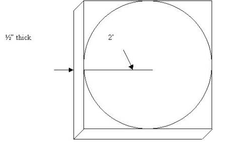
One of the few original design
specifications that never changed was the dimension of the hovercraft. The hovercraft was cut out of a square
four-foot piece of plywood. The
original design called for a smaller radius, however, with one of the goals of
the hovercraft stating one person should be able to ride it, a new radius of 2
feet was decided, thus allowing enough room for one person to hover. Due to this, the plywood needed to be at
least a half-inch thick to support this amount of weight. We decided not to use plywood of any greater
thickness so as to reduce hovercraft weight.
The
hovercraft’s circular origins were created under considerations for the
skirt. First, a square shape would
inherently be difficult to put a skirt on.
Here we lucked out, relying on pure intuition. We did not know until putting on skirts later how difficult it is
to center a skirt. And secondly, the
square corners would puncture the thin nylon of the skirt material. Under considerations of puncturing the
skirt, after cutting out the four-foot diameter circle, the edges were heavily
sanded. Thus, after a few hours of
work, we were left with a four-foot diameter sanded circle.
The
next step involving the hovering of the hovercraft is allowing an air
inlet. We needed to bore a hole in the
circle, however, not too large as to be counterproductive and let out air and
not too small as to not let in an adequate amount of air. Deciding to use a hose from a shop-vacuum as
a guideline, we cut a two-inch diameter circle out of the circle. Once again, after taking under consideration
the placement of both a person and a shop-vacuum, the whole was cut
approximately nine inches off center.
Finally, the hole was also sanded.
The
key element in our hovercraft was to be the thin nylon skirt. Seeing as we could not obtain enough power
to hover off of a blower alone, we had to rely on a pressurized air
bubble. To this extent, a circular
plastic skirt provided the pressure bubble.
We foresaw the intrinsic problem with this; the hovering ability of the
hovercraft lies in the pressure buildup in the thin plastic skirt, any hole or
laceration would inevitably lead to lower air pressure, ultimately leading to
impair the hovering ability. Therefore,
the greatest thickness possible was chosen for the plastic material, in the end
this was a meager six-millimeters.
With
the six-millimeter plastic, an approximately five-foot diameter skirt was cut
out. Even though the hovercraft is only
four feet in diameter, we needed enough extra plastic to inflate so as to rise
the wood off the ground a couple of inches.
What would hinder this would be two factors. The first being that we decided to rely on the original schematic
instructions of using duck tape to attach the skirt. With the duck tape we needed to pull the skirt up a couple of
inches on the topside of the wood, thus allowing enough plastic skirt for the
duck tape to attach to. The second
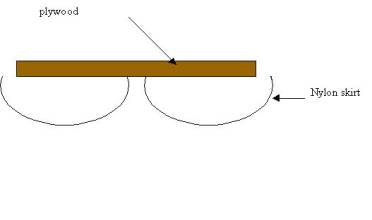
factor was due to the inherent nature of a hovercraft. Hovercrafts in commercial use hover on a
ring of air located on the underside of the hovercraft. There are several reasons for this, the
first being the reduction of surface area for the skirt. This equates to less money spent on the cost
of a skirt, less power needed to inflate a skirt, less time spent inflating a skirt,
and less wear on a skirt. Secondly, in
our case, this gives the hovercraft the ability to hover. This ‘skirt ring’ took on a more doughnut
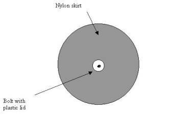
shape for hovercraft. To create this
‘doughnut’ shape, we drilled a quarter inch hole through the center of the
hovercraft. Next we took a quarter inch
bolt and attached a three inch plastic lid around the bolt’s top. Placing the bold through the center of the
skirt, and then through the underside of the hovercraft, we effectively created
the ‘doughnut.’
Figure 2.2 A one quarter inch bolt with a plastic lid was used to lift the center of the skirt.
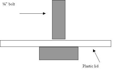
Figure 2.3 Top view of the hovercraft with air inlet installed 9” off center. Also shown is the six millimeter thick nylon skirt coming up from underneath.
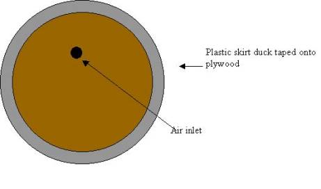
Figure 2.4 and Figure 1.5 A side and bottom view of the ‘doughnut.’
Quite evidently the next step in the process for our hovercraft was the placement, number, and size of ventilation holes. We knew we needed ventilation holes, without them the thin plastic skirt would surely burst due to pressure build up. Also, without a place for the air to escape, the hovercraft could not truly hover. Another factor that played into the placement of the ventilation holes was that the holes needed to be placed relatively close to the center bolt. This would allow the air to escape, forming a pressure bubble inside the ‘doughnut,’ essentially creating the ‘doughnut hole.’ The resulting air pressure buildup in the ‘doughnut hole’ would leave one place for the air to escape, underneath the hovercraft, thus creating the hovering ability. Therefore 12 one and a half-inch holes were cut into the plastic, all six inches from the center bolt.
The hovercraft was then attached to a shop-vacuum and inflated. We allowed one person on to test the abilities of the hovercraft. The person was indeed hovering; air was rushing out from underneath. Another indicator of the hovering ability was the reduction of kinetic friction.
While the hovercraft hovered, it was far from a thing of beauty. The shop-vacuum hardly had the power to lift one person. The nylon skirt began to burst and obtained numerous holes. The duck tape refused to hold the plastic skirt against the plywood. Lastly, the plastic skirt gave out, ripping out the plastic lid creating the ‘doughnut hole.’ The hovercraft was then no longer hovering, and was extremely unstable, throwing its rider.
A more adequate source to provide the air for the hovercraft was needed. With the tearing of the plastic skirt and the inability of the duck tape to attach it, another method of attaching the skirt was needed. Also, a seat needed to be created for the rider.
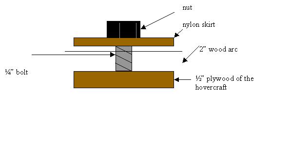
The first problem tackled was that of attaching the skirt. The plastic skirt is the most important element of the hovercraft, without which no hovering will occur. However, plastic has an extremely slick surface. Few substances would adhere to it. This ruled out virtually all tape and glue. Another problem with tape and glue is the amount of time required to attach the skirt and the cost associated with this. Thinking laterally, we were able to come up with the idea of a giant clamp. The clamp would have enough pressure to overcome the slick surface of the skirt.
To create the clamp, four two-inch wide arcs were cut out of ¼” plywood with the same circumference as the hovercraft. Next, thirty-six quarter-inch holes were drilled through the arcs and hovercraft plywood. By bringing the plastic skirt up from underneath, between the arcs of wood and the hovercraft plywood, and then putting bolts through the holes and plastic, we effectively attached the skirt to the hovercraft. Carriage bolts were used to reduce the risk of puncturing the skirt. Also, this allows only one side to be tightened.
Figure 2.1 The hovercraft with the newly installed clamp system.
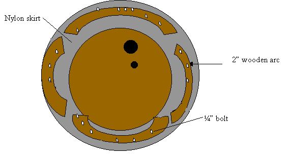
Figure 2.2 A side view of the clamp system.
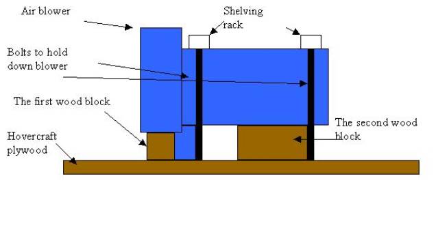
The next process was to obtain a better air unit. We talked to a professor at Oregon Health Sciences University who gave us a high-powered 115 volt 3.5 amp air blower. This unit was could sufficiently supply enough air into the skirt. The air blower was also small enough to be mounted on the hovercraft, eliminating the clumsiness of the previous shop-vacuum. However, the air blower posed an enormous challenge to mount. It was an unusually shaped cylinder. By screwing in two blocks of wood in the right places by the air whole on the hovercraft, we created a base for the blower to rest on. Next, we took two pieces of metal shelving racks and drilled holes into the ends. We then used these to bolt the blower on top of the hovercraft, thus firmly securing the blower. Finally, RTV was used to eliminate any possibility of an air leak where the blower met the hovercraft plywood.
Figure 2.3 A side view of the blower mount.
An interesting note of the air blower is the amount it weighs. The hovercraft now hovers at an angle unless balanced by a person riding it. To help the person riding the hovercraft achieve this balance, we placed a small folding chair on top of the hovercraft. Also, the new air blower provided a sufficient amount of air to hover up to 250 pounds. Lastly, two handles were installed for transportation purposes.
The new improved hovercraft now allowed us the ability to change skirts easier and in a more timely fashion. With the addition of the blower, the hovercraft will remain hovering while in operation. Finally, the hovercraft was ready to measure air pressure.
After reading from various “hovercraft experts” we were unable to determine any information about pressure buildup inside a hovercraft’s skirt. It seems no one has bothered much with the basic component of the hovercraft, the skirt. Blindly setting out to measure air pressure, we first needed to decide upon a method of measuring air pressure.
We read through several
physics textbooks and decided that a manometer would be one of the easiest ways
to register air pressure. A manometer
“is a U-shaped tube partially filled with liquid…The pressure P being measured is related to the
difference in height of the two levels of the liquid” (Giancoli, 242). To create this manometer we took a two-meter
quarter-inch glass pipe and bent it into a U.
We then attached this to a piece of rectangular plywood. Finally, we attached a ruler alongside it to
measure the change in height of the liquid.
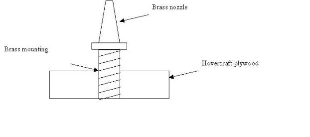
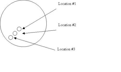
To attach the manometer to the hovercraft we used quarter-inch surgical tubing. The surgical tubing was then attached to a quarter-inch brass nozzle, which was screwed onto a quarter-inch brass mounting. We used three different points to measure the uniformity of pressure; the two points that were not being measured had brass end caps placed over them so as to keep the air pressure inside the skirt. The points were placed at seven-inch intervals from the center of the hovercraft.
Figure 4.1 The manometer is created.
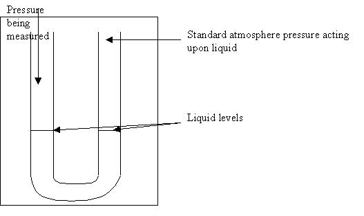
Figure 4.2 A side view of the brass nozzle system.
We measured the air pressure of the hovercraft with no one onboard. We measured from all three nozzle points, noticing a shocking statistic; all three points retained the same pressure reading. Using the formula P= ρgh, where P is pressure measured in N/m2, ρ is density of the liquid, g is gravity, and h is the change in height of the liquid, we came up with our static pressure readings.
We measured the air pressure from these three positions on the hovercraft.
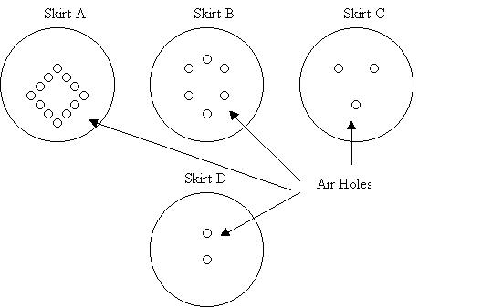
We measured the variations of pressure on these skirts:
The
gathered pressures for each skirt at each location are as follows:
|
|
Location |
|||||
|
|
1 |
2 |
3 |
|||
|
Skirt # |
Change in Height |
Air Pressure |
Change in height |
Air Pressure |
Change in height |
Air Pressure |
|
1 |
1.27 |
12446.0 |
1.27 |
12446.0 |
1.27 |
12446.0 |
|
2 |
1.59 |
15557.5 |
1.59 |
15557.5 |
1.59 |
15557.5 |
|
3 |
2.10 |
20580.0 |
2.10 |
20580.0 |
2.10 |
20580.0 |
|
4 |
No Pressure |
|||||
· The change in height refers to the increase in centimeters that the manometer recorded.
· Air pressure is measured in N/m2
Interpretation and Conclusion
As we were faced with the aftermath of our experiment a vary striking and stern result was fashioned. This is that the air pressure remains uniform at all locations of the hovercraft. The validity of these results is further strengthened by the consistency in which they occurred. Not one data point fell outside of this conclusion making uniformity of air pressure in hovercrafts almost a sure thing.
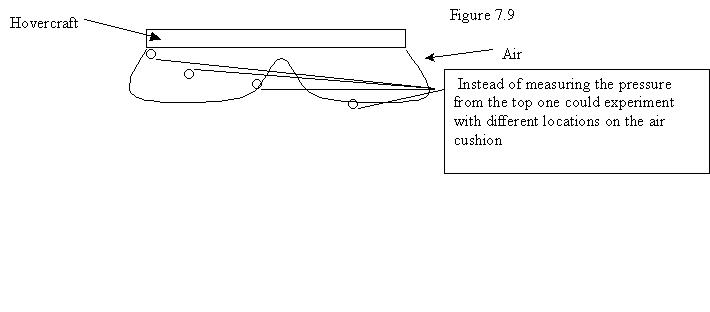
To further expand the study of air pressure and hovercrafts one could attempt to measure various air pressures from different depths on the air cushion as seen in Figure 7.9.
The most efficient skirt
seemed to be Skirt C. This skirt
managed to house the most pressure without bursting. Skirt D was unable to record air pressure because as the air pump
first commenced to fill the skirt with air the skirt burst and all was
lost. For this result, it is easy to
conclude that the air holes in Skirt D didn’t allow enough air to escape the
hovercraft, consequently causing it to burst.
The
reason higher air pressures causes more efficient hovercraft is quite simple.
We observed that the skirts with less air pressure
(skirts A and B) had a harder time achieving the hovering status than skirt C,
which had the highest air pressure.
This especially held truly when we attempted to ride the craft. Aside for hovering betting with our body
weights, skirt C also maintained a greater stability with a passenger
aboard. Both skirts A and B had trouble
staying flat and often tipped the rider completely off the hovercraft.
Wrap Up
We believe that we made the most of the “home made Hovercraft” plans, as we followed the basic designs, but made many adjustments accommodating our goal to measure the air pressure and develop the most efficient hovercraft. Now that the initial construction of hovercraft is complete the logical extension would be to study the effects of propulsion when added to the hovercraft, and find the best ways to achieve movement. After all hovercrafts remain useless if they’re unable to achieve what they where designed to do: move.
Admittedly, our hovercraft will never act as a sufficient mode of transportation being confined by an electrical chord, or may never “look nice”, or may be dangerous to ride. However, it does hover and provide the rider with a near frictionless surface underneath them. Perhaps the most remarkable aspect to our hovercraft is its simplicity and the fact that, yes, its homemade without any fancy kits or space-age parts.
Bogus,
John D. “Air Cushion Vehicle.” The
World Book Encyclopedia. 1998
Chicago. World Book, Inc. Page 181.
Chalin,
John B. “Air Cushion Vehicle.” Encyclopedia Americana. 1996.
New York. Grolier Inc. Page 378.
Giancoli,
Douglas C. Physics 3rd
Edition. 1991. Pentance Hall.
New Jersy.
Goldstein,
Eric. “Howdy.” http://www.ils.nwu.edu/~eric/hover.html
Olshove, Alex. “The Science Project Hovercraft.” The Hover Homepage.
http://members.xoom.com/HoverHome/
Unanimous. “Hovercraft Shape.” http://www.hoverclubofamerica.org/shape.html
http://hovercraft.sdstate.edu/ This is the South Dakota State University hoverpage.
http://www.users.globalnet.co.uk/~potter/ A great site devoted to the history of hovercraft in the English Channel.
http://www.geocities.com/CapeCanaveral/Launchpad/1953/experiments.html
Another site devoted to early hovercraft development.