| Conclusion | Bibliography| Related Links | Research |
Introduction
TopThe word “trebuchet” derives from a Middle French word meaning “overturn”3, and its structure comes from an ancient variation of the sling. The earliest trebuchets were seen in China in about the 4th century BC, called traction trebuchets. To propel the throwing arm, traction trebuchets relied on the power of men pulling on ropes. Counterweight trebuchets, which replaced manpower with some sort of fixed weight or box on one end of the throwing arm, appeared around the Mediterranean in the 12th century. They could fling 300 lb. projectiles at high speeds towards enemy walls1. Trebuchets were far more accurate than catapults because the throwing arm was secured to a pivot rod that prevented most side-to-side movement.
As the counterweight trebuchet became more popular, engineers thickened castle walls to withstand heavier bombardment. Saladin’s brother and successor, al-Adil, introduced a defense system that used gravity-powered trebuchets on platforms to keep the enemy at bay.1
The simplest trebuchet is basically a throwing arm pivoted on a fulcrum. On the shorter end of the arm, there is a raised heavy weight (either fixed or hanging), which releases its potential energy when it falls and lifts the sling attached to the other end of the arm.2 The projectile in the sling is accelerated by being lifted and released at a particular angle depending on the release pin, giving the projectile gravitational potential energy and kinetic energy.
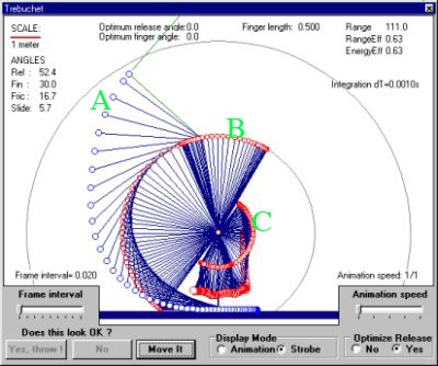
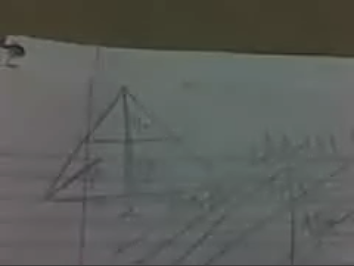
(Photo courtesy of wikimedia.org)
A represents the path taken by the projectile nestled in the sling. At the very bottom of the image, it stays flat because it’s sliding along a trough. B is the path taken by the throwing arm, beginning at the bottom of the image. C represents the path taken by the counterweight (fixed weight or hanging box), starting at the top.
Problem: determine the relationship between the
weight of the counterweight and the velocity of the projectile.
Hypothesis: We believe that a heavier
counterweight will result in a higher velocity because heavier masses have more
potential energy that can be transferred to the projectile.
Materials
Top- 10’ 2x4 pieces of lumber (4)1
- 8’ 2x4 pieces of lumber (7)
- 6’ 2x4 pieces of lumber (1)
- Circular blade saw (1)
- Metal dowel, diameter 1” (1)2
- Metal dowel, diameter slightly less than 1” (1)
- 50 lb. bags of sand (2)
- Bucket with at least 50 lb. capacity (2)3
- At least 32’ of sturdy rope
- About a 1’x2’ piece of sturdy fabric4
- Long piece of cardboard5
- Hook (1)6
- Nail (1)7
- Desired projectile8
- Washers, screws, and nuts9
- Scale10
- Big field (at least 200 feet)
- Measuring tape
- Stopwatch or video camera
2: The diameters are not exact; when in doubt, a larger diameter is better because it needs to be able to support the throwing arm and counterweight box. Likewise, the throwing arm should be well reinforced to prevent splintering.
3: The bucket will be held by the counterweight box, so it is a good idea to secure the lid in case it falls off or its handle breaks (the handle should not be attached to the actual throwing arm). Also, it’s good to have two buckets because one can be used to store the extra sand.
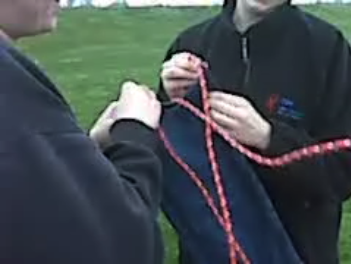
4: The “sturdy rope” will be threaded through this material to create the sling.
5: This will run along the bottom of the trebuchet to create a trough for the sling.
6: The end of the rope that is not released will be tied to this hook.
7: This will function as the release pin.
8: We used a foursquare ball. Flour babies, basketballs, or anything near that general size and mostly spherical is preferred.
9: The washers and nuts should be sized according to the gauge of the dowels because they hold the dowels in place. It is helpful to torque two nuts together on either side of the throwing arm.
10: Use this to measure the weight of the sand in the counterweight bucket/box.
Procedure/Setup
Top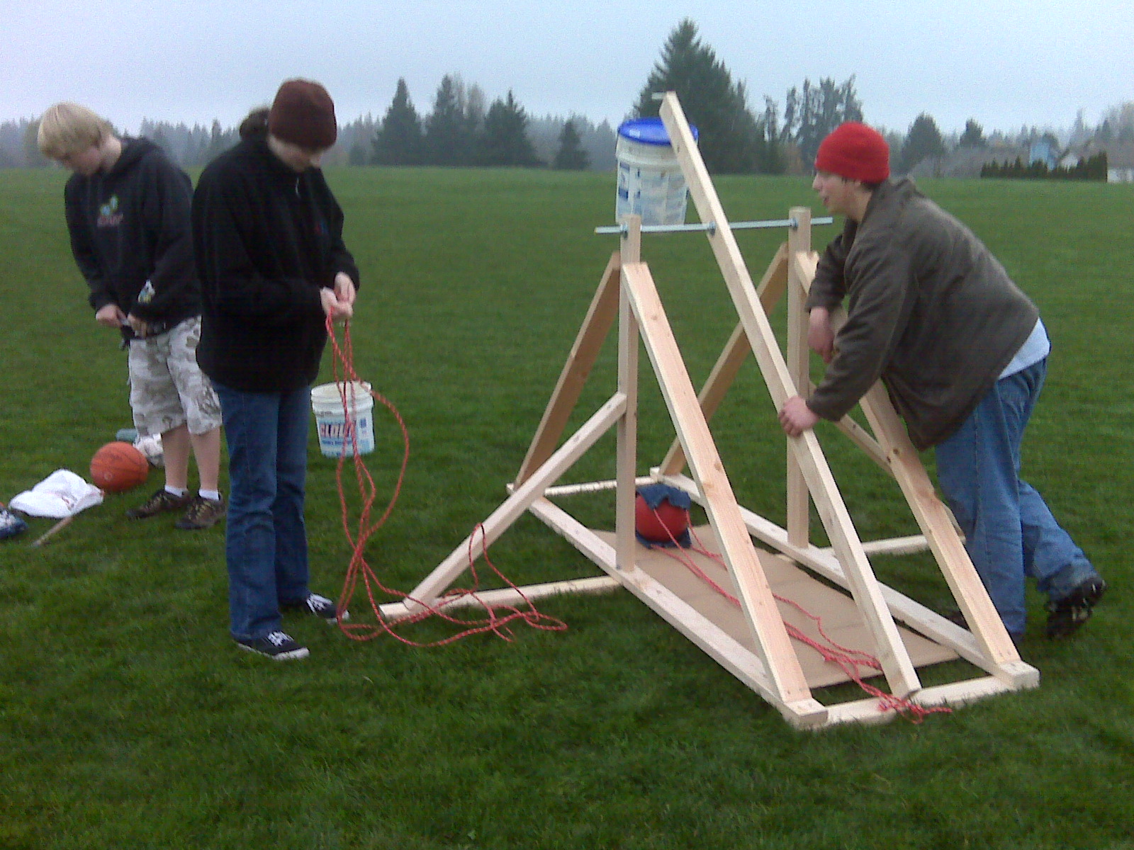
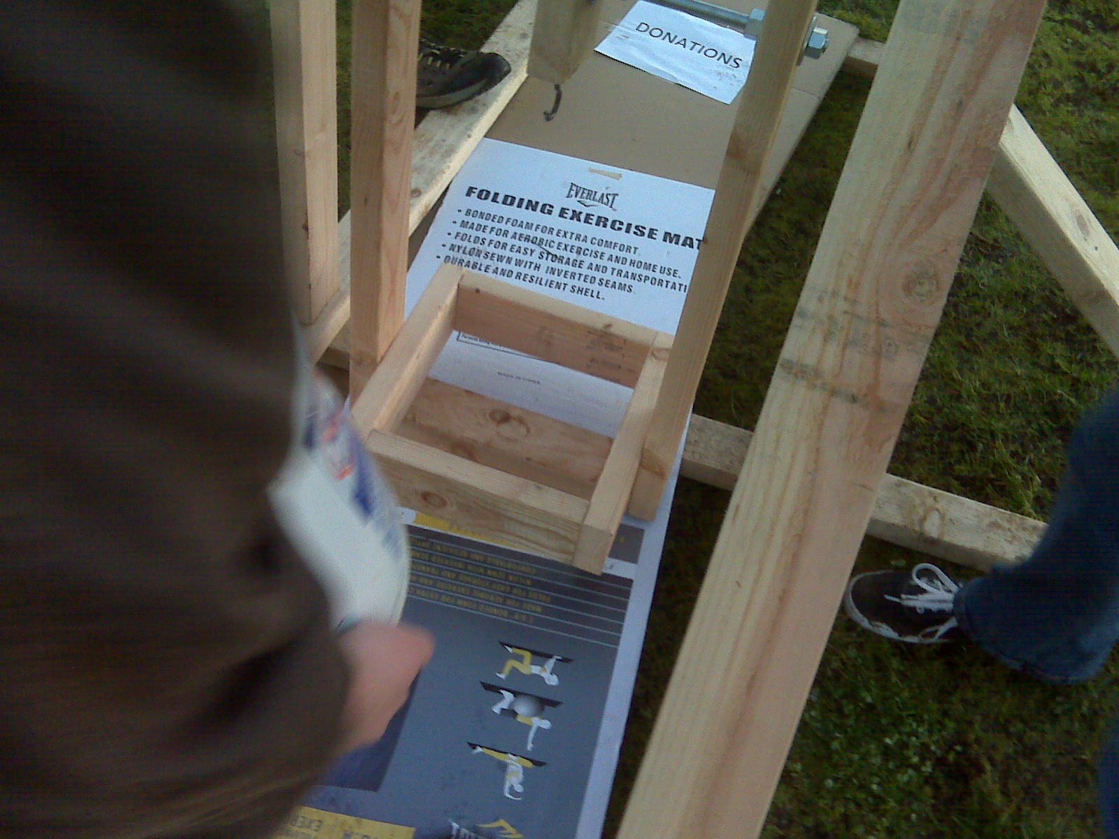
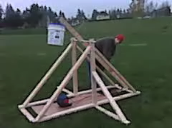
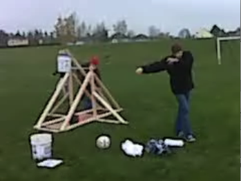
The first image is the entire working setup of the trebuchet before the counterweight box was added. The second image is only of the counterweight box; there is a metal dowel securing the box to the throwing arm. As a matter of safety, make sure that nothing is in the path of the throwing arm or counterweight box when the projectile is released. Beware of over-engineering the trebuchet because lumber is expensive; the amount of wood in the Materials section leaves room for error. Before cutting the lumber, make sure the circular saw is sharp; a dull lathe will burn the wood as it cuts (making pressure-treated wood even MORE hazardous). Staining the wood will further prevent warping and make the trebuchet more “weather-proof”. Be aware of the need for clearance: one end of the throwing arm must clear the ground to account for the hanging counterweight box. To find the optimum release pin angle, bend the pin more upwards; a downward bend will cause it to release the projectile at a near 90 degree angle. Remember that we are trying to attain a 45 degree release angle for the projectile.
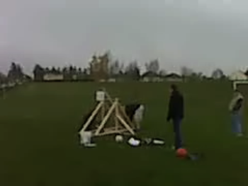
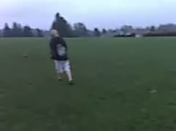
After the trebuchet is built, find a level field with at least 200 feet of clear space. With a 79 lb. counterweight, our projectile traveled about 106 feet. Keep in mind that the projectile will not always fly in exactly a straight line. Pull the loaded sling until it’s as close to under the counterweight box as possible. Make sure the projectile is actually encased in the sling and is not simply being dragged along the cardboard, or it won’t release properly.
There are two ways to release the throwing arm. The first way is to simply have someone strong hold the arm down until it is ready to fling the projectile; however, it is much easier for injury to occur, especially if the throwing arm breaks. The safer way is the attach eye hooks to the bottom of the throwing arm and the back of the trebuchet so that a rod or string can be put through both of them; the rod acts as a sort of “safety” that you pull out when you’re ready to fire.
To record data, simply time the projectile’s flight with a stopwatch or video camera (make sure your time is in seconds). Measure the distance travelled, convert to meters, and use the formula velocity equals displacement divided by time to find velocity. Use the scale to measure the weight of the counterweight.
Data/Analysis
Top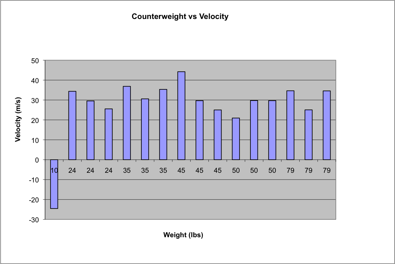
Data File
For each weight, we did three launch trials to account for error. For the 10 lb. weight, however, the projectile was thrown backwards (negative distance) because the sling failed to deploy; that data point is included only to establish a minimum necessary counterweight. The highest velocities perhaps cluster around the 45 lb counterweight, but the data is so sporadic it is difficult to tell; therefore, our results are inconclusive. 79 lbs. was the maximum amount of sand we had to use; perhaps at higher counterweights we could have achieved higher velocities, but no logical predications can be made from current data. There was room for error in this lab in the accuracy of our stopwatch and measuring tape, and perhaps there may have been a slightly different release pin angle that could have increased the potential velocity per counterweight unit. Also, the projectile weight and size could be changed (probably lessened) to increase the potential velocity. Design efficiency was also a factor as this was the first time any of us had constructed a medieval seige engine. The farthest distance the projectile flew was 32.3596m, but it did not have the highest velocity because it took longer to arrive at that distance.
Conclusion
TopThe relationship between the counterweight and velocity of the projectile is not a linear or parabolic increase; rather, its pattern could perhaps follow some sort of bell curve. With engineering modifications to our trebuchet, such as tweaking the release pin's angle or changing the pivot point of the throwing arm, greater velocities could be achieved, and perhaps a clearer relationship between the data could be established.
Medieval trebuchet engineers already knew how to achieve the maximum displacement and velocity for their chosen projectile; our research is nothing new, but it establishes that the “Dark Ages” was full of brilliant physicists, determined to uncover the truths of physics even while plagued by erroneous beliefs that the world was flat and that allowing human waste to run freely through the streets was perfectly hygienic. The many variations on trebuchet design demonstrate the adaptability of this weapon to diverse field conditions and desired effects. Utilized both for attack and defense, this elegant sling has allowed many great conquerors of history to triumph and humanity’s knowledge of physics to increase. The trebuchet has been immortalized in such epic movies as The Return of the King and Prince Caspian, and will doubtless live on to provide other physics students with dynamic and exciting physics projects.
Bibliography
Top1:Wikipedia: Trebuchets
2: “Physics under siege: a trebuchet exploits the principle of the lever to hurl missiles. By considering the conservation of energy, we can predict the launch speed of a missile. Analysis of the resulting projectile motion enables its range to be Physics Review 14.4 April 2005: 26. < http://find.galegroup.com/ips/retrieve.do?contentSet=IAC-Documents&resultListType=RESULT_LIST&qrySerId=Locale%28en%2C%2C%29%3AFQE%3D%28ke%2CNone%2C9%29trebuchet%24&sgHitCountType=None&inPS=true&sort=DateDescend&searchType=BasicSearchForm&tabID=T003&prodId=IPS&searchId=R1¤tPosition=5&userGroupName=tuhs_main&docId=A131279996&docType=IAC&contentSet=IAC-Documents>
3: http://dictionary.reference.com/browse/trebuchet
Wikimedia Image Source
Related Sites
TopWikipedia.org
A good, all-purpose overview of trebuchet physics, history, and design.
Trebuchet.com
Trebuchet kits, physics simulators, and information on other medieval seige engines.
RedStoneProjects.com
A chronological history of trebuchets along with links to kits.
NOVA's Trebuchet
NOVA builds a trebuchet, general info on medieval seige engines and live in the Middle Ages. Also resources for teachers.
SimplyTheBest.com
Ways to get your hands on a trebuchet font!
LegionXXIV.org
Photos of a small trebuchet in action, along with history, evolution, and mechanics of the trebuchet.