Background
   Review of Literature
   Research Question
   Variables
   Hypothesis
   Materials
   Procedure
      Diagram 1
      Diagram 2
   Data Table
   Graph 1
   Graph 2
Background
Before there were guns to fight wars, catapults and trebuchets used to be essential if an army wanted to achieve a victory. The most common trebuchet consists of a long pivoting beam, a very heavy counterweight swinging from a hinge at one end, and a sling with a big rock hooked to the other end. When released the weight drops, the beam rotates and the rock slides down the track in the sling. When free of the track the sling rotates very quickly up and over the beam, and slips off a hook. The rock goes out of the sling and flies away. The projectiles from these weapons had the potential of causing massive damage on any castles or barracks at which they were flung.[1] The more massive the rock, the more destructive the force would be. Of course this seems obvious when one takes into account Newton’s Second Law which states that force is equal to mass times acceleration (F=ma) which in this case is gravity. Early trebuchets were operated by hand, but as technology got better, they were flung with the help of gravity. These are what are called "counterweight trebuchets.”[2] Wheels were also put on these trebuchets to allow for more motion, mobility, and strength. These started to be used in the 1300’s and were kept in use all the way up to the 1500’s when advances in gunpowder exceeded the destructive force of trebuchets.[3]
Review of Literature
Most of the literature used talked about the time period trebuchets were in use, and how they were operated. This was good background knowledge, but it helped little in understanding the mechanics of the weapon which was the focus of the research. There was information found at seige-engine.com that did give designs of certain trebuchets, but not as much on how it worked.[4] By far the best information was found at the University of Carthage’s Physics Department web site because there was not only background information and in-depth trebuchet designs, but also an analysis of how these things worked.[5]
Research Question
If the mass of the counterweight or the the angle at which the projectile is launched is manipulated, how does it affect the distance a projectile travels?
Variables
For the entire project, the distance that the projectile travels will be the dependent variable. There will be two different tests with two independent variables tested. The first independent variable is the mass of the counterweight with the angle of launch at a constant 45 degrees. The second independent variable is the angle at which the projectile is launched, and the mass of the counterweight will also change. For all tests, the mass of the projectile, the position of the fulcrum from the counterweight, and the couillard length will stay constant and air friction will be discounted as the tests will be run in a computer simulation on “Interactive Physics.”
Hypothesis
When the mass of the counterweight increases, the distance of the projectile will travel should increase in a linear path due to the relationship between gravity and the counterweight. As the force exerted on the projectile is equal to the mass of the counterweight times the gravitational constant, when the mass is increased, the force will also increase. Furthermore, because for every action there is an equal and opposite reaction (Newton’s Third Law), the force that is put on the counterweight should be the same force exerted on the projectile. The distance traveled then should be directly related to the mass of the counterweight. In the second test, the distance the projectile travels should be the greatest when the angle of release is closest to 45 degrees. This is due to the fact that there will be no air resistance on the projectile allowing 45 degrees to be the perfect arc for maximum distance.
Materials
For the purposes of this experiment, we have decided to utilize the technology that is available to us. We will be using the “Interactive Physics” program to simulate both the construction and launch of the trebuchet. Although it is theoretically possible to duplicate this experiment in perfect conditions, our research should be the most accurate because the “Interactive Physics” program allows us to negate the effects of air friction and it, in theory, carries out the mathematical formula to make a projection of where the mass should land. We will then be inputting all of our data into Microsoft Excel to ensure that we are able to most effectively evaluate the data.
Procedure
The Initial Design
Because we utilized the computer to carry out our experiment, we selected a program that would allow us to design a fairly complex model of a trebuchet, while maintaining a user friendly interface. The program “Interactive Physics” allowed us to create such a design. We began by making a simple catapult to experiment with the program’s capabilities and limitations. Although we would eventually encounter many problems with the program, it was initially very easy to use.
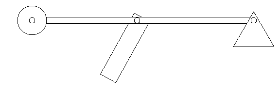
We slowly added parts to the catapult until it began to take the shape of a trebuchet (shown below). This design was too simple, however. Because of the structure of the couillard, we were unable to control the release mechanism and modify the release angle.
If you would like to view this model in real time and have "Interactive Physics" on your computer, click here. Although, as noted above, this version won't work very well.
The Final Setup
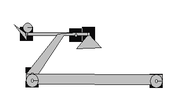
We eliminated the original design and replaced the couillard with something that looked more like this:
If you would like to view this model in real time and have "Interactive Physics" on your computer, click here. Again, as noted above, this is the model that we eneded up using. So it should work better.
By replacing the platform with the ball to rest on with a rigid joint, we could control when the projectile was released. Rather than letting physics dictate the angle of release, we could manipulate the joint to release in terms of the angle of the cross-beam. This allowed us to find the maximal release angle by modifying that angle between the range of 45°-65°.
Gettin’ To Work
Our experiment was relatively easy to carry out once we were able to create a working model of our trebuchet. Unfortunately, sitting in front of the computer for hours clicking the mouse repeatedly to collect roughly 185 data points gets old. Luckily, we were able to plan ahead and spread the work out over the semester to offset the effects of becoming overjoyed with physics.
To begin, we minimized the frame-rate to roughly one frame per .02 seconds and inserted a function into the computer that stopped the program once the projectile had crossed a certain plane on the y-axis. This functioned as both our “ground” and as a way to get an accurate measurement of the distance the ball had traveled. We launched the trebuchet with counterweights on a range of 20-200 kgs at 5 kg intervals. We then repeated this process for the 5 pre-selected angles.
The Experiment
Data Collection and Analysis
Mass (kg) | Distance (m) |   |   |   |   |
  | 45 Deg | 50 Deg | 55 Deg | 60 Deg | 65 Deg |
20.000 | 11.288 | 9.017 | 6.189 | 4.121 | 2.014 |
25.000 | 13.764 | 11.394 | 8.552 | 5.782 | 3.075 |
30.000 | 15.799 | 13.013 | 10.211 | 6.994 | 3.886 |
35.000 | 18.293 | 14.994 | 11.408 | 8.355 | 4.991 |
40.000 | 19.838 | 16.071 | 12.244 | 8.574 | 5.314 |
45.000 | 20.894 | 16.795 | 12.951 | 9.524 | 5.938 |
50.000 | 22.314 | 18.058 | 13.678 | 10.096 | 6.267 |
55.000 | 23.49 | 18.816 | 14.428 | 10.332 | 6.409 |
60.000 | 24.417 | 20.644 | 14.957 | 11.283 | 6.582 |
65.000 | 24.909 | 20.836 | 15.728 | 11.508 | 7.187 |
70.000 | 26.755 | 21.066 | 16.524 | 12.164 | 7.328 |
75.000 | 26.785 | 22.253 | 17.516 | 12.08 | 8.01 |
80.000 | 28.313 | 22.029 | 18.603 | 12.477 | 8.259 |
85.000 | 27.824 | 23.314 | 17.121 | 13.304 | 7.911 |
90.000 | 29.333 | 24.173 | 18.016 | 12.82 | 8.451 |
95.000 | 30.516 | 24.346 | 18.878 | 13.472 | 8.501 |
100.000 | 29.429 | 24.493 | 18.864 | 13.627 | 8.937 |
105.000 | 30.689 | 25.086 | 19.633 | 13.753 | 9.359 |
110.000 | 31.576 | 25.958 | 20.377 | 13.422 | 8.726 |
115.000 | 32.631 | 24.716 | 21.098 | 13.931 | 9.038 |
120.000 | 33.788 | 25.565 | 19.573 | 14.354 | 9.391 |
125.000 | 31.967 | 26.284 | 20.157 | 14.432 | 9.21 |
130.000 | 32.84 | 26.589 | 20.775 | 14.698 | 9.53 |
135.000 | 33.69 | 27.251 | 21.118 | 15.065 | 9.788 |
140.000 | 34.224 | 27.893 | 21.655 | 15.494 | 10.037 |
145.000 | 35.018 | 28.516 | 22.013 | 14.292 | 10.277 |
150.000 | 35.793 | 26.684 | 21.524 | 14.597 | 9.387 |
155.000 | 36.552 | 27.118 | 21.98 | 14.912 | 9.614 |
160.000 | 34.024 | 27.625 | 22.283 | 15.181 | 9.741 |
165.000 | 34.669 | 28.13 | 22.738 | 15.461 | 9.936 |
170.000 | 35.236 | 28.623 | 22.018 | 15.732 | 10.126 |
175.000 | 35.791 | 28.633 | 22.455 | 15.418 | 10.311 |
180.000 | 36.407 | 28.978 | 22.715 | 15.688 | 9.972 |
185.000 | 36.525 | 29.427 | 23.135 | 15.838 | 10.14 |
190.000 | 37.081 | 29.866 | 23.377 | 16.076 | 10.251 |
195.000 | 37.723 | 30.296 | 23.61 | 16.309 | 10.412 |
200.000 | 38.298 | 30.598 | 24.009 | 16.461 | 10.514 |
A version of this table including the graphs below may be found in Microsoft Excel by clicking here.
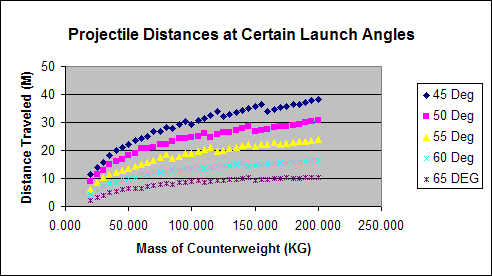
From the data provided in this experiment on Interactive Physics, it is reasonable to conclude that as the mass of a counterweight on a trebuchet increases, then the distance its projectile travels should also increase with it. The data proves the hypothesis correct except for the fact that the distance did not increase in a linear path, it was more quadratic. The data followed a general and consistent pattern of increasing in distance when the mass of the counterweight was increased in intervals of 5 Kilograms starting with 20 KG and ending with 200 KG. There were some glitches in this pattern though which may have been due to computer error. The graph of the projectile distances was generally equal to the equation -8.1551E-4x^2 + .304388x + 8.12756 (where x equals the mass of the counterweight) and they were released at a 45 degree angle each time. The graph was believed to be more quadratic than linear because the longer the projectile is in the air the more time gravity has to act against it and push it down to the ground. So the projectile distances would not increase as rapidly once more weight is added and the projectile is in the air longer. These results support previous, historical experiments as well as Newton’s Third Law of Motion. However, if the experiment were to have been done in real life and an actual trebuchet had been built, then there would have been a point where too much weight could be put on and the projectile distance would no longer increase with the mass of the counterweight. This is because of the stress put on the trebuchet by the counterweight causing possible breakage. The procedure in this experiment was fairly sound, though, because the experiment was run in a computer simulation where air friction was able to be neutralized and human error in building was minimized. It was also possible to manipulate the program so that the projectile would stop at the exact moment it hit the ground, and the computer would give the precise distance the projectile traveled. This eliminated any uncertainty in the distances. If the experiment were to have been done in real life and the trebuchet built by hand, then the results would be more prone to human error and there would be more uncertainty. Of course this does not mean that there were no weaknesses in the procedure. For example, the counterweight did not have a full range of motion and would often hit the base of the trebuchet. This was really only evident when the mass of the counterweight was fairly large. If the experiment was to be done over, the fulcrum length would be made smaller. This may be why the distance the projectile travels does not increase with each interval of counterweight masses.
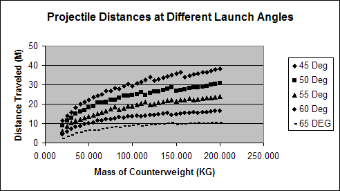
From the data acquired in the second experiment, it is reasonable to conclude that a 45 degree angle of launch is the angle that gives the most distance to the projectile. This data also proved the hypothesis correct. The reason that there were no angles under 45 degrees used is because theoretically, in a program where no air resistance is registered, a 50 degree angle should produce the same results as a 40 degree angle and 55 degree angle should be the same as a 35 (consider the equation distance traveled = (Velocity * time) / cos (angle of launch)s=vt/cosθ). Like in the experiment above, the graphs of all the angles were quadratic in nature. The equation of the 50 degree angle graph was -6.4276E-4x^2 + .23849x + 7.03039, the equation of the 55 degree angle graph was -5.33146E-4x^2 + .1970456x + 4.730941, the equation of the 60 degree graph was -4.0621E-4x^2 +.14637x + 3.401566, and the equation of the 65 degree graph was -3.2198E-4x^2 + .1076695x + 1.20833. This is further proof that a 45 degree angle should yield the biggest results. Since this experiment was basically the same as the previous, the errors and improvements were basically the same. One error, however, that was unique to this experiment was that when the angle got bigger and the mass of the counterweight was not that great, the projectile often did not clear the base of the trebuchet itself, so the distance had to be estimated. This could have caused the results to be skewed. But since this only happened on four separate occasions, and the base was very close to the ground, it was probably not enough to mess up the data. Yet if the experiment were to be done over again, the base would have been built smaller so the projectile distances of these particular examples could have been viewed. Overall, these experiments gave very accurate data due to the fact it was conducted on a computer program. There were some glitches in the data, but the same thing would have happened if the experiment were to be run in real life. So the way the experiment was conducted was probably in the most accurate way possible, and this is the way the experiment would be done if it were to be conducted again.
Perhaps the most interesting thing we noted from analyzing the graphs were that they all seemed to approach a limit as the mass of the counterweight grew infinitely large. When we take the formulas found above and derive them for each angle; by solving the derived equation for zero, we end up with the limit. To begin with the equation for the 50 degree angle, we take the derivative of -6.4276E-4x^2 + .23849x + 7.03039, which is -.00128552x+.23849. When we solve for zero, we see that the limit of the 50 degree angle approaches 185.5 meters. Calculating the rest of the angles we progress downward with approximate limits of:
This data analysis further confirms our hypothesis that the 45 degree angle has the longest distance if the maximum distance the trebuchet will launch the projectile is greatest at 45 degrees. Although this wasn’t part of our original intent of the experiment, it was an interesting trend that we noticed with the graphs.
[1] Trebuchetstore.com: The Trebuchet here. A brief history of trebuchets including an explanation of how they work. There is also a store where you can purchase trebuchets.
[2] The Grey Company: Historic Counterweight Trebuchet Illustrations here. Illustrations and explanations of the different types of trebuchets.
[3] Nathan Stodola: History here. Where and how trebuchets have been employed throughout history.
[4] Eric Ludlam: Seige-engine.com here.
[5] Carrie Pinter et al.: Trebuchets! here. A paper and experiment by physics students at Carthage College regarding trebuchets.
A note from the author (or more appropriately a whine from the author): This entire webpage was coded by hand because I don't own FrontPage. It took a couple hours and I am now mad. Thanks. Brent.
For the infamous Big T poster, click hurrrrr. Note that it is saved as a word document.
Conclusion
45 degree angle 186.6 meters 50 degree angle 185.5 meters 55 degree angle 184.8 meters 60 degree angle 180.2 meters 65 degree angle 167.2 meters Bibliography