An Investigation of the Relationship Between Angle and Range of a Pneumatic Air Cannon
Andre Zhu
Table of Contents .:. Return to Research
Introduction
Methodology
Results
Conclusion
Errors and Experimental Improvements
Background (to Top)
The majesty of a pneumatic air cannon cannot be underestimated. An unspoken tradition of physics lovers is to create one, with the intention of launching innumerable projectiles, and bearing witness to the simple, yet beautiful trajectories these aforementioned projectiles produce. With so many variables to manipulate and control, ranging from barrel length, volume, projectile mass, there are many facets of the air cannon to be explored [1]. The modern day connotations of the air cannon refers to its hobbyist applications, most notably firing common household objects from the hands of those fortunate enough to wield one, whether from own craft or store origin. Now the term ‘air cannon’ refers, perhaps infamously, to its ability to launch spuds and pumpkins at high velocities that would be harmful without proper precautions placed [2]. This has lead many hobbyists to test the physics of the air cannons themselves, and find out the most efficient designs to propagate the farthest ranges, tinkering about with the multitude of variables the air cannon possesses to find the best results, and mitigating variables like air resistance or air friction [3]. The air cannon will always remain a symbol of the aspiring physicist, whether they reside in the countryside, or even in physics classrooms that follow the International Baccalaureate syllabus. The idea of creating a relatively powerful device to launch mostly spherical objects seems like a prospect that would love to be accomplished by a student in this aforementioned IB Physics classroom.
Statement of the Problem (to Top)
The purpose of this investigation is to determine the relationship between angle and range, its general function and where range will be maximized.
Hypothesis (to Top)
The relationship between the angle of the barrel with the ground, the independent variable, and the range, the dependent variable, is that the graph formed between the two will resemble an inverted parabolic function -x^2), and the peak range, represented as the top of the parabola, will occur at 45 degrees. This will occur due to the inherent properties of the right angle, will can be observed through the range equation, stated in terms of velocity, gravity, and sin(θ):
![]()
If the angle between the barrel of the cannon and the ground approaches 45°, the overall sin angle will become 90 (as 45*2). Thus, sin(90) will equal 1, and the range equation will be the largest it can possibly reach, as it becomes a 1/1 ratio.
![]()
Therefore, the apex of the range should be found at 45°.
Controlled variables in the experiment include, but are not limited to surrounding air temperature and pressure, length and radius of the PVC pipes, and therefore the volume of the air tank, and radius and mass of the projectile in question.
Experiment Set-Up (to Top)
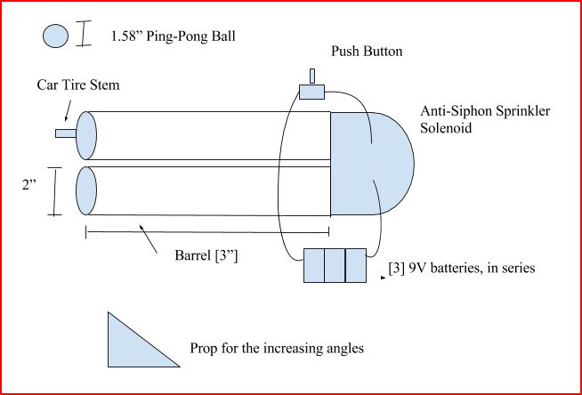
Figure 1: A web-based rendition of the pneumatic air cannon utilized for this experiment.
Materials (to Top)
Cannon:
(1) 2” (diameter) x 10’ length of PVC pipe (for tank/barrel)
(1) 1”(diameter) x 6” length of PVC pipe (for connecting solenoid with reducers)
(2) 1” to 1.5” bushings
(2) 1.5” to 2” ABS reducers
(1) 1” Anti-Siphon Sprinkler Valve (24V)
(1) 2” PVC Rounded End Cap
(1) Car Tire Stem
(1) Air Gauge (maximum 120 PSI)
(1 container) PVC Glue and Primer
(1) Measuring Tape
Wiring for the Cannon:
(3) 9V Batteries (27V altogether)
(3) 9V Battery Snap Connectors (Optional: batteries can be placed in series, snap connectors or alligator clips can be used for ease of use)
(1) Push Button
(1) Solder/Soldering Station (Solder was used instead, but connectors can be used instead)
Electrical Tape
Procedure (to Top)
Assuming creation of the cannon is complete, a preliminary task is to go to an undercover location with a flat surface. First, the valve stem is unscrewed, and the cannon placed flat on the ground, and the projectile is loaded into the barrel of the air cannon. Then, the cannon is pumped to 50 PSI, and placed contently on flat surfaces that prop the cannon up to be supported at the desired angle. Afterwards, the button is pressed, and the projectile is launched. There will be a measuring tape secured to the ground with adhesive, and a spotter will mark the point where the projectile lands.This process will be repeated for every 10 degrees, starting at 10°, to 80°, but also including 45°. 10 trials will be done for each respective degree measurement. Thus, there will be 9 total different angles measured (at 10, 20, 30, 40, 45, 50, 60, 70, 80 degrees, respectively). The cannon will be repressurized between trials.
Data Processing and Graphs (to Top)
|
Angle (±0.5°) |
Range (±0.0127 meter) |
|
10 |
14.934 |
|
20 |
21.56 |
|
30 |
22.268 |
|
40 |
24.267 |
|
45 |
24.823 |
|
50 |
24.55 |
|
60 |
21.156 |
|
70 |
14.438 |
|
80 |
5.354 |
Table 1: Shows the angle in degrees of the barrel, with increments of 10 starting at 10 and ending at 80, including 45, and range, all of them averaged by the 10 trials.
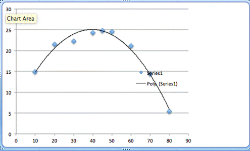
Figure 2: Graph that shows the angle taken in degrees and range of the projectile in meters. The black line indicates a curve of best fit, while the blue points are respective points in Table 1.
Evaluation (to Top)
The hypothesis, which states that the relationship between the angle of the barrel and range of the projectile would create an inverted parabolic graph, appears to be substantiated, given the curve of best fit given for the graph being reasonable, so the hypothesis appears to be true. The apex of the range is at approximately 40 degrees, when seen graphical, but that is most likely attributed to systematic error, possibly in pressure in PSI or a slight change in angle when launching the projectile
Given the nature of the range equation, it seems reasonable to conclude that the experiment and data gathered reflects the type of graph created. If one were to conduct the experiment with changes in the variables that were kept constant in these trials, for example higher pressures or larger projectile mass/radius, one could expect a stretching or compressing of the graph, but the overall function shape should be constant through any possible variable change. There are errors that are seen in the tools that measured angle and range, but they should have not too much of an effect on the outcome of the experiment, as they are mostly negligible given the distance that is traveled by the projectile, and can be easily fixed by more precise measuring tools and automation.
Errors and Experimental Improvements (to Top)
Although the experiment gave a relatively stable parabolic equation as hypothesized, there are certainly a multitude of variables that would create a more accurate experiment and make the trials more precise.
A first consideration is that due to some of the materials, notably 1” to 2” reducers, not being easily accessed, a compromise of a transition from 1” - 1.5” - 2” PVC reducers and bushings were required to adequately construct the cannon in the time period of its construction. Therefore, air flow was not optimized, possibly because of small leakages or gaps through the PVC glue, as the air flow had to expand to fit the 2” PVC pipe. Thus air flow may not be distributed in the most even manner, and may have affected the range.
Secondly, the gauge utilized had an uncertainty of ± 0.5 PSI, which, although not too bad, is still a noticeable uncertainty bracket, equal to the ± 0.5 cm uncertainty of the tape measurer. It would be ideal to minimize this key component of measurement by using a more accurate pressure gauge, as the analogue one used during the experiment leaves a more accurate instrument to be desired. A tangible type to obtain is a digital car tire gauge, but of course, the inherent issue with this approach is that there will be inevitable leakage once the stem is unscrewed, and before the cap is placed back on. An ideal solution would be to have a digital gauge implemented into the cannon itself, as the certainty of the gauge is a very important variable, where uncertainty should be minimized to the greatest degree possible.
Another source of error is the assumption that all of the air’s energy when the solenoid is released is transferred to the ping-pong ball when it is released. However, due to the discrepancies between the radii of the PVC barrel and ball, respectively, of (1.58:2) inches, it creates possibly a 0.2” buffer on every side of the ball. Therefore a certain amount of energy from when the solenoid releases the air to when the ball leaves the barrel is not being transferred, and ‘escapes’ the barrel. This can be mitigated with a closer ratio, for instance the 2.70” diameter of a tennis ball and a 3” diameter PVC pipe, which could yield better results.
A potentially important error to lessen is air resistance and friction. Regarding air resistance, it is simply an inherent error that is tied to being outdoors, enveloped under the atmosphere of the Earth, but theoretically, this can be mitigated by performing the experiment in a zero gravity environment, that is pressure and temperature controlled-environment.
There are great amounts of improvements that could be made to the experiment to create empirical data that more fits a negative parabolic curve, and the aforementioned improvements are but a selection of the multitude that are possible.
Bibliography (to Top)
[1]: US Air Force Measures Potato Cannon Muzzle Velocities." MIT Technology Review. N.p., 8 May 2013. Web. 25 Dec. 2016.
[2]: Schupak, Amanda. "How It Works: The Artillery-Grade 600 MPH Pumpkin Cannon." Popular Science. Bonnier Corporation, 25 Jan. 2010. Web. 5 Jan. 2017.
[3]: Giancoli, Douglas C. Physics: Sixth Edition. Upper Saddle River, NJ: Prentice Hall, 1998. Print.
Related Links (to Top)
The Projectile Velocity of an Air Cannon – Comprehensive models of a few air cannons and some complex calculations that were useful to realize possible errors, regarding air flow.
The Physics of Punkin’ Chunkin’ – Larger scale considerations of the parabolic trajectories inherent to angular launches, which was useful in a focal sense.
Internal Ballistics of a Pneumatic Potato Cannon – Although a different medium is utilized, overall the site was useful to better understand the internal mechanisms of an air cannon.
The Exit Velocity of A Compressed Air Cannon – Gives calculations of velocity of an air-compressed cannon, so gave some insight into how far a smaller projectile would be launched.
Mobile Air Cannon Design – A really useful webpage about the origins of the air cannon and the continued desire among enthusiasts to create air cannons as hobbyists.