1/26/2012
|
Jessica Blank, Jena Hughes, Jennifer Jenks |
![]()
The Hovercraft is based on the simple principle of a vehicle that is able to float above a smooth surface on a cushion of air. The first recorded design for an air cushion vehicle was created by Swedish designer and philosopher, Emmanual Swedenborg in 1716 ("Hovercraft by Year"). In order to create a cushion, air is vented underneath a vehicle into a curtain which traps the air, forcing the vehicle to float just above the ground or water. The air cushion allows the vehicle to move freely because of a lack of friction between the cushion and the ground ("How does a Hovercraft Work?"). With this reduction of friction the craft will conserve momentum and glide across a surface without stopping as quickly as a vehicle that had friction acting upon it. As per Newton’s First Law, the craft will always move in a straight line until acted upon by a force ("Hovercraft").
In this experiment, the volume of the air flowing into the cushion must be adjusted accordingly to account for the weight of the vehicle as well as the weight of a possible rider. Air pressure will have to be sufficient enough to allow the craft to move freely across the ground. Weight must also be balanced in order to keep the craft floating and level (Hovercraft). A hovercraft is statically supported upon a cushion of pressurized air, generally from an onboard downward-directed fan. The picture below shows how the air vents moving through the hovercraft create the air cushion below in order for it to move:
1) Propellers 2) Air currents 3) Fan 4) Flexible skirt (or Curtain)
A hovercraft is able to glide freely due to the fact that the vents of slowly moving, low-pressure air are ejected downwards against the surface close below it creating the air cushion. The air is trapped beneath the hovercraft by a flexible skirt. The trapped air cushion greatly reduces the friction of the hovercraft. (“Science Buddies”)
The relevant physics principals to this investigation are as follows:
● Motion is a change in position measured by distance and time.
● Speed is the rate at which an object moves.
● Acceleration is the rate that speed or direction changes.
● Inertia may refer to an object's "amount of resistance to change in velocity" (“Physics Classroom”, “Motion Graphs”)
Newton’s laws of motion may also be helpful to our investigation. They are:
1. Every object in a state of uniform motion tends to remain in that state of motion unless an external force is applied to it.
2. The relationship between an object's mass m, its acceleration a, and the applied force F is F = ma. Acceleration and force are vectors; in this law the direction of the force vector is the same as the direction of the acceleration vector.
3. For every action there is an equal and opposite reaction. (“Newton’s”)
The purpose of this experiment is to create a functioning hovercraft that will essentially eliminate friction under the craft causing a gliding action in relation to Newton's first law.
If a hovercraft is built using the process of a prototype and then the making of the real thing then one will be able to find the optimum positions, airflow, and size of the craft to create a stable and frictionless vehicle.
● Wood
● Duct Tape
● 2 leaf blowers
● Hammer
● Staple gun
● Sander
● Exact-o knife
● Staples
● Zip ties
● Hose clamps
● Hot glue gun and glue
● Wooden pole
● Spray paint
● Heavy duty plastic
● Pressboard
● Plastic lids
● Saw
Our design process followed two steps, we began with a quick prototype to help understand the important design parameters. The creation of the prototype basically follows the same structure as the actual craft except for materials. We took a wooden board and cut a hole the size of the leaf blower nozzles. We then cut and folded the plastic around the edges of the board leaving a bag for air. At this point we secured the airbag and cut out a grommet from an old plastic lid. We secured the grommet with the staple gun and then duct tape. We then cut holes around the duct tape areas to allow for air to flow out. At this point we secured the one leaf blower and started testing making notes of possible improvements. With the prototype we varied our flow from the blowers to achieve optimum uniformity. We also varied the placement of the holes around the grommet for stability and balance and varied the location of the rider for the right center of gravity and balance.
Our first step in creating our second hovercraft was gathering all the materials needed. We started with the wooden board and used a saw and sander to curve the edges. We learned from making the prototype that the air may flow better and the hovercraft may be more stabilized with curved edges. Using the hand saw, we cut holes on opposite sides of the board which were the size of the nozzle for each leaf blower. After doing this, we laid out the plastic and sized it to the board, making sure to give about 5.5 centimeters of margins of plastic around the board for proper filling and securing. We then cut the plastic and secured it to the board using a staple gun, hammer, and duct tape. In order to make the grommet, we cut out a rectangle from a piece of pressboard according to the dimensions on the diagram. We then used a staple gun and duct tape to secure the grommet to the board. We cut holes about 4.5 centimeters in diameter around the grommet using an exact-o knife. We knew from the prototype experiments that this size and number of holes would allow the plastic to fill up evenly, as well as allow for just enough air to escape in order to create a nice curtain of air underneath the hovercraft. We placed the leaf blowers in their designated holes and turned them on in order to test this. We fixed any additional holes that we noticed using duct tape and kept testing and fixing the places where excess air was leaking until we were satisfied. After this, we secured the leaf blowers onto the board using duct tape, wooden blocks, and metal zip ties in order to assist the leaf blowers in not falling over. We then made our seating arrangements using a black dinner chair that we sawed the legs off and put boards around. We tested the hovercraft by turning on the leaf blowers and having one person sit on the seat. We looked for issues with stabilization, propulsion, air leaks, etc. We found that designing some kind of propulsion system would be beneficial to the person on the hovercraft in order for her to go in the direction she chooses. We decided to create a fan propulsion system using a box fan, cardboard, and duct tape. We cut the cardboard and folded it into a hexagonal shape and taped it onto the box fan. We placed the system on the back of the hovercraft and turned on both leaf blowers and the fan. We soon learned that the fan, even on its highest setting, was unsuccessful in generating enough thrust to propel the hovercraft forward. It also seemed to add a lot of weight to the back of the hovercraft, causing it to be unbalanced. We decided to resort to using an oar-like object for the passenger to use to control direction and propel herself forward. We found a giant wooden pole and used hot glue on the ends in order for the pole to push off the ground better. We then decorated it, along with the hovercraft. After all this, we tested the hovercraft again and looked for any other issues that could easily be fixed, but found none. The lift, balance, and stability were good.
The following is the diagram that one can reference when looking for a specific part. The first diagram shown is a top view of the craft and the second is the bottom view. Things not shown are the blowers, clamps, chair, and other things that are up to the builders discretion.
Top
Bottom
Top
(All measurements are made in centimeters)
Bottom
(All measurements are made in centimeters)
Our results are a functioning hovercraft that achieved the goals of a near frictionless vehicle. We were able to make the vehicle glide effortlessly only to the limit of the extension cords. If the cords did not tether it down we believe that the vehicle would continue for a very long time until stopped. We were able to obtain an idea of the optimum positions of certain pieces of the craft in order to minimize friction and maximize stability.
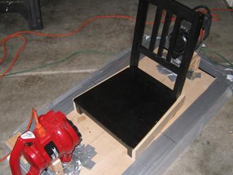
This is a picture of the final product.
In order to improve on our hovercraft we applied physics concepts to adjust the model accordingly. Round edges were added to the sides of the craft to allow air flow to move more easily. The rounded edges reduced air resistance along the sides and streamlined the air flow. It also reduced the friction between the air particles and the side of the craft. A grommet was placed in the middle of the air bag underneath the craft and holes were cut in the plastic around it. This was due to the basic physics principals needed to make the hovercraft as frictionless as possible. Air is forced out of the holes in the plastic and into the space between the grommet and the ground. The air underneath the hovercraft is at a higher pressure than the air outside the chamber. Pressure then builds and is forced to escape through the space between the plastic and the ground. This small layer of air between the ground and the plastic significantly reduces the amount of friction, allowing the craft to glide across the ground. The lower the friction the better momentum can be conserved. This is why the grommet has to also be equidistant to the edges of the craft so the air will escape evenly underneath it. With more pressure the craft will become more balanced, making it easier for someone heavier to ride. This is because the air is forced under the craft faster and at greater quantities, providing a more stable surface against adjustments and shifts in weight (the air will still force its way underneath the plastic). Two leaf blowers were used in our second to deliver this increased pressure of this. Despite the vast improvements in our second model there were still many sources of potential error. Measurements were not exact and there could have been holes in the plastic allowing uneven amounts of air to escape. We could have compared the hovercraft to models of different proportions in order to optimize its efficiency and balance.
For future improvements, we believe a wider board would provide more room lateral shifts in the center of gravity by putting the support for our cushions further out towards the edges. We would also recommend gasoline powered leaf blowers so that the craft would not be tethered by extension cords. This plus a steering mechanism (possibly a third leaf blower) would allow for a truly ridable craft. With this we could have tested the hovercraft on different terrains so it could operate in a variety of places. Although the experiment could have been improved on, the original goal of the experiment succeeded. By creating a prototype, and then adjusting the model through experimentation, we manipulated physics principals in order to create a rideable hovercraft.
"Hovercraft." Web. 30 Oct. 2011. <http://www.darylscience.com/Demos/Hovercraft.html>.
"Hovercraft Year by Year." Hovercraft Museum Charity Website. Web. 30 Oct. 2011. <http://www.hovercraft-museum.org/years.html>.
"How Does a Hovercraft Work?" Science Fair Project Ideas, Answers, & Tools. Web. 19 Oct. 2011. <http://www.sciencebuddies.org/science-fair-projects/project_ideas/Aero_p033.shtml>.
"The Meaning of Shape for a Velocity-time Graph." The Physics Classroom. Web. 30 Oct. 2011. <http://www.physicsclassroom.com/class/1dkin/u1l4a.cfm>.
Poarch M. "Motion Graphs." Web. 27 Oct. 2011. <http://www.mysciencesite.com/motion_graphs.pdf>.