Variability in the Performance of Composite-Propellant Rocket Motors
David Harris, Moira Todd, Mackenzie Humble, Martin Locklin
1/24/2011
The modern rocket was conceived by Robert Goddard when he connected the supersonic nozzle with the liquid fuel combustion chamber in the early 1900s[i].They were further developed by the Germans in the years leading up to World War II, and were perfected by largely the same group of scientists in the post-war Soviet Union and United States. Originally developed for military applications, rocket technology has been cross-applied to power mankind’s exploration of space.
Rocketry has always been defined by the progress of armatures, beginning with Goddard and continuing today with hobby rocketry. Until recently, the line between hobby rocketry and professional sounding rockets (suborbital research rockets) was clear cut at about 40 kn/s of impulse[ii]. However, with changes in government regulation, the advent of more powerful hobby motors, and the expanse of amateur avionics, that line is now blurred. The first amateur team to reach space did so in 2004, and many other suborbital shots have followed. The motors that power these vehicles are often originally developed for cruise missiles and other military technology, and then spun off as commercial products.
Today, high power model rocketry is a thriving hobby and industry. Consisting of every rocket propelled vehicle from 3.3 lbs to rockets weighing more than a thousand pounds at launch, the spectrum of high power rocketry is immense. This experiment will focus on the lower end of the spectrum, with motors that are still considered “model rocket motors” and not “high power motors.”
Rocket motors are the technological implementation of Newton’s Third Law—for every action, there is an equal and opposite reaction. All rockets accelerate mass from their combustion chamber out of a nozzle at high velocity, moving a larger mass at a lower velocity in the opposite direction[iii]. The accelerated mass at high velocity is the result of a chemical reaction between the fuel and the oxidizer. In solid propellant rockets, the fuel and oxidizer are mixed together with the help of a binder in a solid state.
 Traditional
Estes-type model rocket motors are made of compressed black powder, which are
cheap to produce at small scale, but become very fragile at motors larger that ‘E’
class. Motors E class and above use
Ammonium perchlorate composite propellant
(APCP), a combined fuel and oxidizer mixture that results in a high energy
propellant[iv]. The
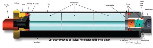
propellant takes on a rubbery consistency, and is cast into cylindrical grains
that are inserted into a metal or phenolic-epoxy casing. Most composite motors
burn from the inside out, with the geometry of the propellant grains determines
the profile of the burn.
Traditional
Estes-type model rocket motors are made of compressed black powder, which are
cheap to produce at small scale, but become very fragile at motors larger that ‘E’
class. Motors E class and above use
Ammonium perchlorate composite propellant
(APCP), a combined fuel and oxidizer mixture that results in a high energy
propellant[iv]. The
propellant takes on a rubbery consistency, and is cast into cylindrical grains
that are inserted into a metal or phenolic-epoxy casing. Most composite motors
burn from the inside out, with the geometry of the propellant grains determines
the profile of the burn.
The two governing bodies of high power rocketry, the National Association of Rocketry (NAR) and the Tripoli Rocketry Association (TAR), require that motors for hobby use be certified by one or more of the respective testing committees for safe operation and performance to spec. Each has a reciprocal agreement with the other to honor certification agreements. The NAR does its testing at MIT, while TRA does its testing at its own facilities.
The certification process involves the static testing of at least two motors (usually three), measuring the thrust produced as a function of time. For the G class motors that this experiment is testing, the total impulse must not have a standard deviation greater than 6.7%, and the average thrust must not vary by more that 20% between motors when corrected to sea level @ 20 degrees C[v].
As the certification data is not published in its entirety, it is a mystery to most fliers how exactly their motors are performing in relation to specification. The purpose of this investigation is to determine the variance in the total impulse and the average thrust in three firings of a G class rocket motor. The hypothesis is that the three motors should be within TRA and NAR specification for certification, meaning the motors should be within one standard deviation of total impulse and the average thrust should not vary by more than 20%. The independent variable will be three randomly sampled G class rocket motors of the same type, and the dependent variable will be the total impulse and average thrust. Controlled variables include the testing conditions and ignition system of the static test stand setup.
*It should be noted that TRA has an exemption for research (experimental) motors, flown at specific launches under controlled conditions. The motor characterization process used in this test is applicable to characterize small scale research propellants before scaling them up to larger and more expensive testing procedures.
· Test stand
o Three 2x4 blocks about 8 inches tall
o Test stand base
o 29mm ID cardboard tubing
o 48” of aluminum angle
o 50N force probe
o Epoxy
o Wire to attach force probe to lever
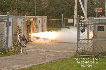
· 3 or more Aerotech G40 rocket motors (67N (15lb) maximum thrust, 3 second burn)
· 60 feet of wire
· Alligator clips
· 12 volt battery
· Weight
· LoggerPro software
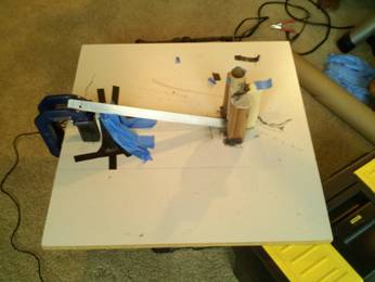
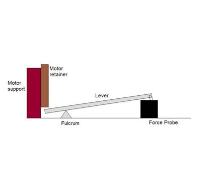
A test stand was designed that would satisfy three factors- safety, cost of construction, and usability. It was built on an old cabinet drawer, using a tube that was the same inside diameter as the motor outside diameter, 29mm. This cardboard tube was supported by 2x4 blocks epoxied to it with high strength Proline epoxy. A window was cut out of the side of the tube with a dremel tool to allow the lever, made of aluminum angle, to slide through. Depending on the rigidity of the aluminum angle, it might need to be doubled up and epoxied together. A fulcrum (aluminum angle) is situated such that when the motor fires, it pushes down on the end of the lever, and the other end pulls on the force probe some distance away.
This design trades some simplicity for safety and workability. The motor is fired downwards towards the ground and into a nest of 2x4 blocks. The plume (about a foot long) and hot gases are directed towards the sky and away from the ground and flammable materials. However, the lever is induced to get the motor in an upright position. While it is possible to fire the motor horizontally, a broken test stand results in a missile, where the motor harmlessly flies into the ground when fired upright. We were limited by a 50N force probe, and as even these low thrust motors exceed 50N of thrust, we needed a lever to reduce the load on the force probe.
On a day where the outside temperature is approximately 20˚ C, conduct trials by first reading and follow all of the safety instructions packaged with the rocket motors. Remove the ejection charge located at the top of the motor under the red cap. Insert the igniter through the nozzle and down the slot in the propellant. Insert the motor into the motor retainer and ensure that it slides freely and contacts the lever. The lever might need to be propped up with something that will easily be shoved out of the way by the force of the motor, such as some folded paper.
Cut the wire into two 30 foot lengths and attach the alligator clips to the ends of both. The other end of the wires can be left bare. Attach the alligator clips to the igniter as per the motor instructions. Start data logging on the LoggerPro software, and stand back 30 feet. Touch the two wires to the 12v battery to fire the igniter and ignite the motor. Wait 15 seconds after the motor burns out to allow any residual propellant (which continues sputtering for some time) to burn off. Stop the data collection. Dispose of the igniter and the spent motor casing as per the motor instructions.
There are two values that we are interested in from each of the motors: burn time and thrust, needed to calculate average thrust and total impulse.
First, the conversion from the lever must be applied to all of the data.
f1d1=f2d2
F= Force
D=distance
The fulcrum of the lever ended up being 20cm away from the motor, and 10cm away from the force probe, thus f1 needed to be multiplied by 2 to correct to the “true” value.
All of the data was run through an Excel spreadsheet to correct the “raw” data to “true” data, and then re-graphed in LoggerPro to use the analysis tools in the software.
The burn time of the motor is extrapolated out of the force probe data by taking the point at which force starts to increase and when it tapers off (Appendix I)
To calculate average thrust, all of the thrust data points are divided by the total number of data points. (In Appendix I, SUM(C1:C168)/168)
The Integral tool in LoggerPro is used to calculate the total impulse, which in this case is measured in Newton-seconds (corresponding to the force and time axes).
|
Trial |
Burn Time (s) ΔS≈0 |
Average Thrust (n ) ΔN≈0 |
Total Impulse (ns) ΔNS≈0 |
|
1 |
3.34 |
17.75 |
59.42 |
|
2 |
3.62 |
35.12 |
127.7 |
|
3 |
.22 |
9.805 |
1.039 |
|
Certification |
3.1 |
37.2 |
113.7 (15=SD) |
The results, taken at face value, do not support the hypothesis that the motors will consistently perform within the required certification specifications. However, only trial #2 was really problem free, and it does support the hypothesis, being within 1 standard deviation of the total impulse (127.7ns measured v 113.7ns certified) and well within 20% of the average thrust (35.12n v 27.2n certified).
At first glance, the results do not support the hypothesis that the motor performance would conform to certified specification. The data varies wildly between 1ns and 127ns of measured impulse and 9.8n to more than 35n measured thrust. It is impossible for a motor to vary by that much, and when combined with difficulties encountered during the testing, it is evident that the experimental setup was flawed.
The results were mired because of limitations on the force probe. We were forced to design in a lever to dampen the forces to under 50N being “felt” by the probe. While the static test stand design was solid on the interface between the motor and the lever, it wasn’t solid between the force probe and the lever on the opposite end. It’s almost impossible to create a zero-play attachment system that would transfer 100% of the force on the lever directly to the force probe without modifying the force probe itself. We were forced to attach the two with a loop of wire, which ended up having far too much flexibility to get an accurate measurement.
The flexibility of this wire attachment system can be demonstrated when comparing the graphs of the actual thrust curve and the closest measured thrust curve.
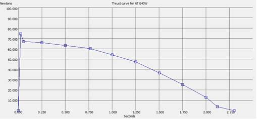
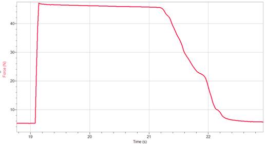
While the impulse and average thrust came out to be within tolerances, the curve is markedly different. The force probe flatlines during the first 2 seconds of the burn, even though the lever should be ensuring that there is never more than 40N of thrust registering on the probe. It appears as if the stretching of the wire attachment system might be creating additional force readings. There might also be some calibration issues that need to be corrected, as physically the probe should not be saturated out during the burn. It also doesn’t characterize the regressive portion of the burn very well, meaning that the wire is probably stretching or compressing.
The other two trials were even farther from the established curve. The first trial produced very low impulse and thrust values even though the shape of the curve was decent, and we tightened the wire connection before the second trial (described above).
The third trial was just one quarter second spike, then nothing. One reason for this might be that a much more powerful igniter was used (as it was the only one available). It produced a much more powerful kick at ignition, and the kick might have saturated the force probe or broken a connection somewhere.
Knowing these sources of error, the most important improvement for a follow-on experiment would be to find a more accurate force probe with a higher maximum force and eliminate the lever. All professional test stands measure the force of the motor directly, as the lever introduces too much variability into something so precise.
The hypothesis is still a valid one, as it has not been conclusively disproved here. A future experiment using appropriate materials and equipment would be able to test it with much higher fidelity and a much higher probability of success.
[i] Hamilton, Calvin. “A Brief History of Rocketry.” Kennedy Space Center. Web. 2001. <http://www.solarviews.com/eng/rocket.htm>
[ii] Coker, John. "ThrustCurve Hobby Rocket Motor Certification." ThrustCurve Hobby Rocket Motor Data. Web. 26 Oct. 2010. <http://www.thrustcurve.org/certification.shtml>.
[iii] Brain, Marshall. "HowStuffWorks "Rocket Physics: The Space Baseball Scenario"" HowStuffWorks - Learn How Everything Works! Web. 2008. <http://www.howstuffworks.com/rocket1.htm>.
[iv] Braeunig, Robert. "Basics of Space Flight: Rocket Propellants." Www.braeunig.us. 2008. Web. 15 Nov. 2010. <http://www.braeunig.us/space/propel.htm>.
[v] Coker, John. "ThrustCurve Hobby Rocket Motor Certification." ThrustCurve Hobby Rocket Motor Data. Web. 26 Oct. 2010. <http://www.thrustcurve.org/certification.shtml>.
Related Sites
1. http://hyperphysics.phy-astr.gsu.edu/hbase/rocket.html -Explains varying mass as it relates to rocket propulsion; formula that accounts for changing mass
2. http://www.braeunig.us/space/propuls.htm -Explains thrust, combustion, exhaust velocity and other concepts present within the research paper
3.http://www.howstuffworks.com/rocket.htm - Basic description of the concepts neccessary for the rocket to combust and take off the way it did. (Every action equal and opposite reaction/ Newton's Second Law)
4. http://microgravity.grc.nasa.gov/education/rocket/rktfor.html -Briefly explains lift and weight as it related to thrust-indicative to how our rocket took off and reacted
5. http://www.lunar.org/docs/handbook/motors.shtml -Detailed account of how rocket motors function-Neccessary in understanding the logistics related to rocket motors