Introduction Method Results Discussion Links Go Up
Catapults have been used for many centuries. In our project we will be using a similar structure to determine how placement of weight on a catapult-type structure affects velocity. Our project will use a structure similar to the one below except we will attach one heavy object on one end while having a lighter weight object on the other end. We will be measuring the velocity of the smaller object using SUVAT formulas.
Moving the
pivot point to find relationship between the distance and pivot
point.
The type of device that we will use is similar to
that of an early Trebuchet or Catapult discussed by Robert Colborn in the world
book encyclopedia. He states that
these early versions were developed after the original catapults and found to
launch with a greater velocity due to a stationary piece that the launching arm
would pivot on. It is common
knowledge that the heavier the weight being dropped on to the side that is
opposite the lighter weight the further the lighter weight will launch.
But we are going to see if the placement of the weight has any affect on
the velocity. With these variables
staying constant how will the velocity vary when the placement of the weight is
moved from one end to the other?
Statement of the Problem:
Review
of Related Literature:
Throughout history there have been many different types of catapults.
The types have changed in size and in design.
But many have kept the equidistance pivot point (Newton Armstrong). That fact we shall keep the same, but what the people
throughout history have failed to do is experiment with the placement of the
weight. The weight will be
interchanged through seven placement points for us to determine the relationship
between our two variables.
In
a research project similar to the one that we will perform Alastair Black and
Scott Muller found that the further the weight was towards the top of the lever
the greater the velocity. They also
noticed that the further towards the top they placed the heavier weight the
higher the object would fly.
With
the different types of launching devices it has been studied and discovered that
in general the older catapults used in wars were more effective than the larger
trebuchets and ballistas (“How Stuff Works”).
The studies that have been done have stated the average war catapult
would launch 500-1,000 feet (150-300 meters).
We are going to dissect their findings and on a smaller scale, see if
when the placement of the weight was changed if the catapults could have
launched with a greater velocity making them even more effective and shoot
possibly even farther.
Statement
of the Hypothesis:
In the research that we are going to do we will be determining the relationship between the position of the weight and the velocity of the small massed object. Our prediction for the project is that the center placement point between the pivot and the non-launching side of the arm will provide the marble with the greatest velocity. We also believe that the point with the greatest velocity will provide the furthest displacement.
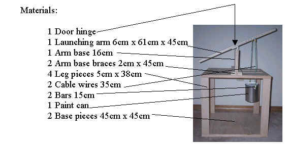
For our structure
we took one base piece and attached one of the four legs to each of the corners.
Then we attached the other base piece on top of the four legs.
Then after we had attached the two base pieces we cut slits in the top
base piece to enable the wires attached to the weight to swing freely.
After the slits were cut and the two base pieces were attached we
connected the top base (with the slits) to the arm base.
We added a block on each side of the arm base to give support.
Then we attached the hinge that served as a pivot point for our launching
arm. Then we drilled seven holes, 2
cm apart, in between the pivot point and end of the arm. We put them through the
side of the launching arm to serve as placement points for the weight.
We attached the launching arm by connecting the other end of the hinge to
the launching arm. Then we placed one of the two metal bars through the
first hole and then connected the weight with the two cable wires.
The weight we placed into a small paint container to keep the weight
compact.
The reasoning for our
experimental design is that we knew that we couldn’t drop the weight onto the
launching arm because there would be too many uncertainties.
We also figured that it would be too difficult to attach the weight on
top of the launching arm each time. So
we decided to hang the weight below the launching arm to give us more accurate
data and it would allow us to keep the weight attached without having to change
the setup for every set of data.
For gathering the data we used SUVAT problems to solve for the velocity. Knowing that the horizontal acceleration is zero, vertical acceleration is -9.8m/s^2 and that the final vertical velocity is also zero we only had to measure the horizontal and vertical displacement. For measuring the horizontal and vertical displacement we used a cardboard background that was marked off with measurements. We filmed the launching and took it frame by frame to figure out at which point it was the highest. Then we determined how far the highest point was from the launching height to get the vertical displacement. For the horizontal we used a similar process. We filmed it to see at what point the marble reached the highest and how far away that was from the original launching position. Then once we had that information it was easy to solve for the initial velocities. All of the equations that we used to calculate the initial velocities are all below. We inserted all of the data from the first hole closest to the pivot to give you a better idea of how we solved for our answers. The first three equations are from SUVAT and the last is for the vector component to combine the initial horizontal and vertical velocities.
v2
=
u2 + 2as (0)2 = u2 + 2(-9.8)(.200 3.92
= u2 1.98
m/s = Initial Vertical Velocity s =
((u + v)/2)t (.200)
= (((1.98)+(0))/2)t .200 = .99t .202
s = t s =
ut .5 at2 (.435)
= u(.202) + .5(0)(.202)2 .435
= .202u 2.15
m/s = Initial Horizontal Velocity
|
H |
|
V |
|
|
S |
|
|
??? |
U |
??? |
|
|
V |
0 m/s |
|
0 m/s2 |
A |
- 9.8 m/s2 |
|
|
T |
|
A2
+ b2 = c2 (1.98)2
+ (2.15)2 = c2 8.543
= c2 2.92 m/s = initial velocity
|
|
Horizontal
|
|
1 |
2 |
3 |
4 |
5 |
Average |
|
0.08m |
0.439 |
0.439 |
0.430 |
0.432 |
0.435 |
0.435 |
|
0.10m |
0.499 |
0.508 |
0.501 |
0.503 |
0.502 |
0.503 |
|
0.12m |
0.532 |
0.539 |
0.541 |
0.548 |
0.540 |
0.540 |
|
0.14m |
0.612 |
0.620 |
0.615 |
0.616 |
0.622 |
0.617 |
|
0.16m |
0.630 |
0.638 |
0.636 |
0.641 |
0.635 |
0.636 |
|
0.18m |
0.675 |
0.678 |
0.681 |
0.679 |
0.680 |
0.679 |
|
0.20m |
0.698 |
0.702 |
0.706 |
0.703 |
0.701 |
0.702 |
Vertical
|
|
1 |
2 |
3 |
4 |
5 |
Average |
|
0.08m |
0.203 |
0.20 |
0.200 |
0.201 |
0.196 |
0.20 |
|
0.10m |
0.233 |
0.229 |
0.236 |
0.232 |
0.234 |
0.233 |
|
0.12m |
0.245 |
0.247 |
0.244 |
0.249 |
0.246 |
0.246 |
|
0.14m |
0.243 |
0.240 |
0.238 |
0.241 |
0.240 |
0.240 |
|
0.16m |
0.247 |
0.248 |
0.252 |
0.247 |
0.250 |
0.249 |
|
0.18m |
0.251 |
0.253 |
0.254 |
0.252 |
0.253 |
0.253 |
|
0.20m |
0.254 |
0.252 |
0.250 |
0.251 |
0.247 |
0.251 |
The next three tables show the velocities from our catapult. The table on the left shows the initial horizontal velocity for each distance and the table in the center shows the initial vertical velocity for each distance. On the right, the table shows the initial horizontal and vertical velocities combined with vector components. These are the initial velocities for the marble.
Obviously
the graph above is not a straight line, but it is close, which shows our data’s
accuracy. The reason the line above isn’t straight is because with all
experiments, there are uncertainties that have to be accounted for. Our two
biggest uncertainties are in measuring the horizontal and vertical
displacements. Each one has an uncertainty of ± .005 m.
Another very small uncertainty would lie in our hinge.
It has the slightest movement. This
uncertainty would be about ± .0001 m. Together
those add up to ± .0101 m. To find
the actual velocity uncertainty in m/s we divided the ± .0101 m by the time it
took for the marble to reach the highest point.
These are the uncertainties we used for our velocities.
A new table of the initial velocities and their uncertainties are below.
|
|
Velocity |
||
|
0.08m |
2.92
m/s ± .0496 m/s |
||
|
0.10m |
3.15
m/s ± .0465 m/s |
||
|
0.12m |
3.26
m/s ± .0458 m/s |
||
|
0.14m |
3.53
m/s ± .0455 m/s |
||
|
0.16m |
3.59
m/s ± .0451 m/s |
||
|
0.18m |
3.73
m/s ± .0447 m/s |
||
|
0.20m |
|
Our hypothesis that the center placement point between the pivot and the non-launching side of the arm will provide the marble with the greatest velocity was incorrect. Through our data we see that as the placement of the weight moves further away from the pivot point, the velocity increases. The reason that there is always a positive increase in velocity is due to the fact that each time the weight placement is moved further out, there is a longer distance to fall. When the weight is attached to the end point it stands at the highest distance above the arms stop position. Therefore the weight shall travel the furthest causing the launch velocity to increase due to the acceleration caused by the distance the weight falls. So the velocity should increase the closer the weight gets to the end that is not launching the object. Our data did not support our hypothesis.
With further investigation we would make more placement points extending all the way to the end of the arm. We would see if the very end does as our data has shown, launch the marble with the greatest velocity. Another possible way to further our research would be to see what affect the closer holes have on the velocity of the launching arm and see if it continues with the pattern of our data or if it will turn the graph into some kind of bell-curve.
How stuff works, Inc: Catapults
Good basic knowledge of catapults and different variations.
Catapults in Greek and Roman Antiquity:
History and Reconstructions of older catapults.
All about Catapults: Catapults and Trebuchets
This page showed good pictures of other types of catapults.
Catapults: Weapons of destruction (pictures)
More diagrams of trebuchets in action.
Catapults: History and Pictures
Gives a detailed explanation of where catapults came from and why.