Exploring the Relationship between Pressure and
Velocity of a Projected Object from a
Pneumatic Cannon
By
Tim Archer & Constance Wong
Introduction and Background Information
Exploring the Relationship between Pressure and
Velocity of a Projected Object from a
Pneumatic Cannon
By
Tim Archer & Constance Wong
Introduction and Background Information
Introduction to Pneumatic Cannons and the Relationship between
Pressure and Velocity of a Projectile
Background:
For many years now, combustion has been used in such devices as engines and weaponry. Combustion rests on the fact that pressure (as well as the introduction of heat and specific chemicals, which shall not be applied to this investigation), is responsible for energy and work output. When applied to weapons, specifically pneumatic cannons, their pressure becomes most important to energy, work and velocity. It is the factor that greatly impacts the velocity of the object being shot from the cannon, as well as the energy the object receives. The air pressure built up in the chamber of the cannon acts upon the projectile, causing it to leave the cannon.
Statement of the
Problem:
The purpose of our investigation is to find the optimum pressure needed to achieve the greatest velocity of an object shot from a pneumatic cannon. The cannon will be set at a 45 degree angle and will project an object of constant mass, while the variable will be the pressure pumped into the chamber.
Review of Literature:
Gasses, such as air, have neither a fixed volume nor shape, and instead expand to fill their containers (Giancoli). Pressure, or “force per unit area,” can be found using the force acting upon the area and the surface area, or through the density of the liquid and its volume (Giancoli). In any case, in relation to a pneumatic cannon, the air pressure is built up in a chamber, that when released through a valve, expands into the rest of the barrel and thus pushes out any object inside (Pneumatic Cannons). This is explained further through Sir Isaac Newton’s third law of motion, stating that “to every action, there is an equal and opposite reaction,” as well as the laws of conservation of momentum and energy (Giancoli). From these laws we know that the pressure built up inside of the chamber has a force that will act directly on the projectile that will react with an equal and opposite force. Like rocket propulsion, the object is propelled out of the cannon while the gun recoils backwards, and thus momentum and energy are conserved.
Numerous investigations into the myriad aspects of the pneumatic cannon have been explored, ranging from the impact of varying barrel lengths to differing masses, or changes in pressure. We will focus on pressure as a possible function of velocity. As for our design of the cannon, such websites as “Blackrain's Electronically-fired Air Cannon,” “Pneumatic Air Cannons,” and “The Spudgun Technology Center” have been helpful in providing us with ideas.
Hypothesis:
We believe that the higher the pressure, the higher the velocity, which suggests a direct correlation between the two. The optimum pressure will be reached when the air in the chamber reaches the maximum volume that the chamber can hold.
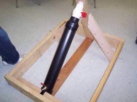
First, the cannon itself needed to be constructed. This involved a significant amount of ingenuity. Ultimately, we decided to use PVC pipe and a hand-pull trigger with two separate chambers: One for the storage of the compressed air, and the other as a barrel to release the golf ball. The two chambers were connected by a large ball valve which could keep the storage chamber airtight, but when released, would allow maximum air to flow through the barrel. Also a 3 in. to 2 in. reducer was used between the ball valve and the pressure chamber. All of this was connected with PVC glue and a little patience. The pressure itself came from an electric air compressor and was fed intravenously through another smaller ball valve into the pressure chamber of the cannon. This valve was connected through a drilled hole in the base of the cannon and with PVC glue and J-B Qwik cement and hardener. The back end of the cannon was topped of with a hard plastic end cap. Our materials for the cannon are as follows:
1 PVC pipe - 3 2 ft long, 1 2 in inside diameter (This is the barrel)
1 PVC pipe - 2 ft long, 3 in inside diameter (This is the pressure chamber)
1 Ball Valve - 2 in inside diameter (This is the release mechanism)
1 Air Compressor Connection Ball Valve - 5 in long (This feeds pressure in to the chamber)
1 PVC End Cap - 3 in fit
1 PVC Reducer - 3 in to 2 in
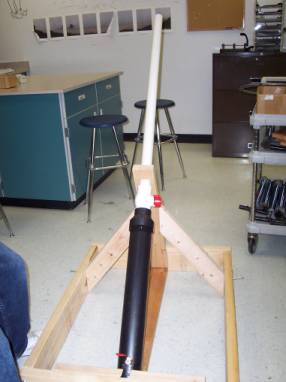
The next element of our set up was the base of the cannon itself. For our particular experiment the cannon needed to be set at a 45-degree angle and needed to be stable on all sides. To accomplish this, a base was built that was square in shape and was 3 ft long by 2 ft wide. This base square was constructed of 2 x 6 boards and lag bolts. The next element was a stabilizer piece of wood that would also act as the angle mechanism. This wood was cut at a 50-degree angle at the base (which, relative to the length of the cannon and the height of the wood itself, created a 45-degree angle for the cannon) and a small 2 x 2 in. window was cut at the top of the wood itself to receive the cannon barrel, effectively keeping it balanced. This piece of wood was attached to two legs of wood that kept it steady on the left and right sides. This contraption was connected with lag screws. A final piece of wood ran the length of the base square and connected to either end with bolts. When this base was constructed it allowed for the cannon to slide in and rest at the back end with the barrel through the window at a 45-degree angle. Our materials for the base are as follows:
2 2x6 boards 3 ft long
2 2x6 boards 2 2 ft long
2 2x4 approx 8 ft in length to be cut in to 4 smaller pieces of
2- 2 ft long
1- 3 ft long
1- 2 3/4 ft long
The final construct looks like this:
The final elements were a 3 gallon air compressor, a long tape measure (100 meters), multiple golf balls, and a stop watch.
The procedures for this experiment are as follows:
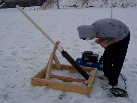
First, connect the air compressor to the cannon via the small ball valve
Fill the pressure chamber of the cannon with as much pressure as you so choose (This is accomplished by releasing the small ball valve lever and allowing pressure to flow in. This can be measured on the pressure gauge of the compressor)
Load a golf ball in to the barrel of the cannon
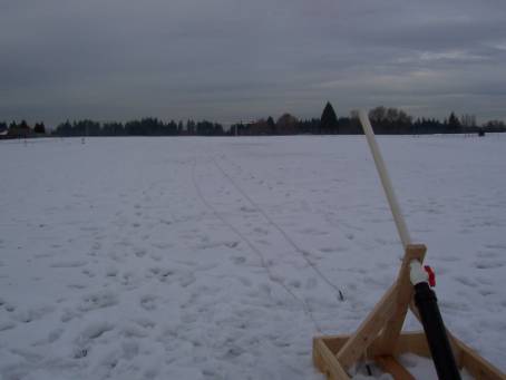
Lay the tape measure from the end of the barrel of the cannon to some distance away. (It works best to stretch it to its maximum distance)
Then, you are ready to fire. Plant your feet firmly behind the cannon and take hold of the release lever with your right hand. Pull back with all your might and watch the ball soar. (It helps to have people already waiting to find where the golf ball lands)
Time the ball in the air and stop when it lands.
Measure the distance from barrels end to the balls landing place
Calculate desired values using information gathered
|
Data
Collection: |
|
|
|
|
|
|
|
|
|
|
|
|
|
|
|
|
|
|
|
|
|
|
|
|
|
|
20 PSI |
|
|
40 PSI |
|
|
60 PSI |
|
|
80 PSI |
|
|
Trial |
Distance
(m) |
Time
(s) |
|
Distance
(m) |
Time
(s) |
|
Distance
(m) |
Time (s) |
|
Distance
(m) |
Time
(s) |
|
1 |
55.2 |
2.7 |
|
94.9 |
3.3 |
|
134.9 |
4.1 |
|
124.9 |
3.8 |
|
2 |
56.1 |
2.7 |
|
83.5 |
3.1 |
|
148.9 |
4.4 |
|
149.2 |
6.2 |
|
3 |
56.6 |
2.7 |
|
95.4 |
3.3 |
|
141.2 |
4.2 |
|
141.5 |
6.0 |
|
4 |
35.3 |
2.4 |
|
90.4 |
3.2 |
|
133.2 |
4.0 |
|
161.7 |
7.0 |
|
5 |
48.9 |
2.6 |
|
95.1 |
3.3 |
|
134.2 |
4.1 |
|
119.2 |
3.8 |
|
6 |
49.4 |
2.6 |
|
100.8 |
3.5 |
|
125.0 |
3.9 |
|
154.3 |
6.4 |
|
7 |
58.9 |
2.7 |
|
89.1 |
3.2 |
|
128.5 |
3.8 |
|
144.8 |
6.1 |
|
8 |
73.5 |
3.1 |
|
78.9 |
3.1 |
|
142.2 |
4.3 |
|
139.1 |
4.3 |
|
9 |
69.6 |
2.9 |
|
95.0 |
3.3 |
|
139.7 |
4.2 |
|
152.4 |
6.4 |
|
|
|
|
|
|
|
|
|
|
|
|
|
|
Averages:
|
|
|
|
|
|
|
|
|
|
|
|
|
|
55.9 |
2.7 |
|
91.5 |
3.3 |
|
136.4 |
4.1 |
|
143.0 |
5.6 |
|
|
|
|
|
|
|
|
|
|
|
|
|
|
Initial/Final
Velocity: |
|
|
|
|
|
|
|
|
|
||
|
|
|
|
|
|
|
|
|
|
|
|
|
|
|
24.6m/s |
|
|
32.1m/s |
|
|
38.8m/s |
|
|
37.5m/s |
|
Calculations:
Velocity = Ö[(range/time)^2 + (g*time/2)^2]
Example:
20PSI:
v = Ö[(55.9/2.7)^2 + (9.8*2.7/2)^2]
v = 24.6m/s
Discussion:
Our results show that our hypothesis was mostly correct; there is a fairly direct correlation between the pressure used in the air cannon and the resulting velocity of the projected ball, as seen in the following graph:
However, as the pressure increases to 80 PSI, the velocity of the ball slightly decreases. The first three pressures show a strong direct correlation, but the graph seems to level out at the end. This means that the optimum pressure for our air cannon that would achieve the greatest velocity, or the cannon’s maximum capability, may lie at approximately 60 to 70 PSI.
Reasons for this downward slope in the graph lie in these limitations of our cannon as well as other possible errors that may have occurred during our experiment. At very high pressures it becomes increasingly difficult to turn the release valve to let all of the pressure out at once; we did not have the luxury of a solenoid to fire the cannon in a consistent manner. Another major area for error is measurements of the distance of the ball from the cannon, the time in which the projectile spent in the air, and the exact amount of pressure pumped into and released from the cannon. We had to use multiple measuring tapes to estimate the distance the ball traveled, which is a very difficult task when measuring such far distances. The trajectory of the ball was also not in a straight line, which affected the accuracy of our measurements. When timing the time the ball spent in the air, it was very difficult to see the ball or discern when exactly it hit the ground as it blended in with the surroundings. It was also difficult to fill the air tank with exactly a certain amount of pressure, as the pressure gauge was quite small. The air also sometimes slightly leaked from the cannon, making the amount of pressure released onto the ball inconsistent. Other factors that may have affected the accuracy of this investigation may be due to air resistance, wind, uneven terrain, and other simple human errors.
For future experiments, numerous improvements could be made on our design and procedures to improve the quality of our results and reduce uncertainty. First, let us start with the simple fixes: the measuring device could be much longer (200 meters or so). This would ensure accurate length measurement. Second, the hand release valve could be replaced with a solenoid. This would eliminate the few split seconds between the pull of the trigger and the release of the pressure that exist when in our experiment. If that human error could be eliminated, the pressure would no doubt be more accurately released (that is, the amount of pressure coming out of the barrel would always equal the pressure gauge on the compressor). For some slightly more difficult improvements, a new piece of the base could be constructed which would keep the cannon from rotating side to side. This would keep the trajectory of the golf ball straight. In our experiment, this was a bit of a problem. Also, the length of the cannon barrel and the volume of the pressure chamber are variables that can be changed. An increase in either of these measurements would result in increased distance and velocity. Finally, if it were possible, the ability to perform this experiment inside would eliminate the problems of air resistance, uneven terrain, and any extreme cold or heat that may affect the outcome of the experiment.
“Blackrain's Electronically-fired Air Cannon”
<http://www.stinggroup.addr.com/cannon/cannon.html>
Giancoli, Douglas, C. Physics, Principles with Applications. New Jersey: Prentice Hall,
1980.
“Pneumatic Air Cannons.” <http://www.angelfire.com/il/pneumaticspud/index.html>
“Pneumatic Cannons.” XINVENTIONS. 2003
<http://www.xinventions.com/home.htm>
“The Spudgun Technology Center” 2003 <http://www.spudtech.com/>