Kevin Bailey
David Glindmeyer
Kevin Pruyn
Table of Contents
The trebuchet is an ancient weapon of warfare, which was first invented and used in the civil war. “It was a successor to the catapult; it could take heavier rocks and projectiles, and fling them farther, with more accuracy” (Fuzzball). It was primarily used as a siege weapon, and one of the most powerful ones at that, along side battering rams, ballistae, and siege towers. Missiles for these powerful machines were mostly rocks, however any combination of ammunition imaginable was used even dead bodies with deadly diseases (some of the first know uses of disease warfare). Many trebuchets even had the ability to launch over 300 pound stones over a quarter of a mile (Carlisle). Modern trebuchets of physics, however, often find themselves using interesting and unique new forms of ammunition, from small pumpkins to large live people. Trebuchets utilize a strong yet lightweight arm usually with a sling attached on the ammunition side, with a heavy counterweight (approximately one hundred times heavier than the missile) on the other side of the arm (Miners).
There is also an important background knowledge that is necessary in areas of linear kinematics and vectors. In addition to researching the history and developments of trebuchets, it is important to know just how to properly, build, operate, and evaluate one. It was key, for instance, in all of the examples that we observed for the angle of the launch to be at 45-degrees if the optimal distance was to be achieved. One must also be very aware when studying this, that if a projectile is in fact launched at 45°, then the initial vertical and initial horizontal velocities are equally distributed because of course both the sine and the cosine of 45° are equal to (Ö2)/2. We have compiled some very good ideas form our sources on how best to achieve an effective and consistent firing method, however it is also very likely that we will have to utilize our ability to determine whether or not we are actually firing at 45°. TOP
In our making of, and in our studying of the trebuchet, we plan on testing the mass of the counterweight in relation to the mass of the missile. In doing so we intend to find the optimal ranges for launching our projectiles. We intend to examine this relationship by both algebraic and graphical means in order to determine the effect of moderately weighted to increasingly heavier counterweights in relationship to a statically weighted projectile. In our case, this projectile is a standard sized baseball.
This original intent, however, simply lent itself to a mini experiment in its own. I hypothesized from earlier research that if a counterweight of about 100 times the mass of the projectile were used, then the greatest distance would be achieved. In our preliminary tests, this quickly became very apparently true. Using a counterweight that was within ten pounds of the 100:1 ratio yielded descent results, while using weights outside of this parameter resulted in horrible, nearly immeasurable data points. No data point less that 40 pounds resulted in enough force on the baseball to discharge it farther than about 30 feet. Going above the ratio didn’t seem to make much of any difference at all, so we finally wound up using 81.5 pounds after much trial and error. We found that although this is actually 260.8 times the specified 5 oz or .3125 lbs. baseballs, it was in fact the optimal counterweight. Nevertheless, just about any weight it seemed over about 50 or so pounds didn’t result in any noticeable varied data. We soon turned our attention to other parameters.
It became clear to us that a much more influential variable would probably be the release angle of our projectile. In some ways this is actually very similar to the problem of too little counterweight, which always seemed to result in too high of release angles without enough initial horizontal velocity. Our problem shifted to how best determine 1) which of our trials were actually shooting at 45° 2) was 45° the actual optimal firing angle and 3) is this relationship supported by a theory that hang time is related to total range if a projectile is in fact fired at that 45-degree angle. TOP
The content of the sites that I visited that had to do with trebuchets ranged from how-to designs, avid patrons of the history of ancient warfare, and of course many fellow students or amateur scientists reporting their own experiences and results regarding the old physics conundrum. I found that Russell Miners for The Grey Company had by far the most useful site. Another web page by the same man (a link from the former) provided some exceptionally interesting insight. On this page he describes a small homemade trebuchet that he made with a 3.5-kilogram counterweight that could launch glass marbles up to 23.5 meters. This was very interesting to us and to our design of our trebuchet. This is because in comparison with larger trebuchets designs, distance seems to be directly related to counterweight mass, but also is all the more important at such a small proportion. We realized that a similar (larger) trebuchet to this “Cheese Chucker” with a counterweight that is some 50 times heavier may only launch its missiles some 10 times or less farther. So this leaves us with an important decision to make on how large our trebuchet should be. Review of this site in combination with our research at the Plumber Pumpkins farm helped us to decide on the hanging basket trebuchet model. TOP
I hypothesize that there
will be natural variations in time and distance.
These variations will be based on the tightness of the sling, the
distance traveled of the counter-weight, and the straightness of the arm.
The greatest variable that I believe will lead to diverse results will be
the launch angle. It is my hypothesis that when actually fired at a 45-degree
angle, the longer the time that a projectile remains in the air, the farther
that said projectile will travel. I
also predict, however, that due to difficulties in measuring a correct 45-degree
angle, most attempts to launch at exactly this angle will be off. TOP
We initially decided to under this project several months ago and swiftly began the tedious task of building a trebuchet. With it we decided that we would launch ammo of an undetermined and possibly varying material (in order to create a dynamic parameter). Some other parameters that we at first had in mind to modify included release angles, materials, counter-weight, height, velocity, etc. Doing this we believed that we should be able to study many fields of physics including conservation of energy, conservation of momentum, and linear kinematics. To begin our research, on Saturday, October 26, 2002 we took a trip to Plumper Pumpkins Farm in Hillsboro, OR to observe their annual trebuchet pumpkin launching fest. There we obtained much information that we can use in the design and planning of our own trebuchet. The trebuchet that we observed there was made out of wood and steel. It was about 6 ft. by 8 ft. on the base and 14ft. high, it had 1000 lbs. of steel counterweight, 6-10 lbs. ammo (pumpkins), and on average it launched those pumpkins about 400 ft. The man there gave us valuable design information such as plausible rope sling extensions to the arm, which add much force to the ammunition without much weight on that end. We were able to look at his design and see how we should place pins to control the release angle, and were surprised to find out that for him 45° was not the optimal release angle. The trebuchet there also used a cleaver wooden slide for the first 5 ft. at the beginning of the launch, which holds the pumpkin in place that is being dragged my the sling rope. After observing that trebuchet, there became a very good chance that we would follow his design. For instance, we also chose not to have wheels on our trebuchet, because as the man pointed out it does not make much difference, if your counter-weight is free swinging instead of fixed. We also thought it likely that we would also use an electrical motor to cock our trebuchet instead of human strength, if we so chose to build it that large (it turns out that we didn’t). All said, the trip provided some great preliminary research.
When we initially made our design on what to shoot and how to do it we planned on shooting apples, all of similar mass, and then varying our counterweight. The apples that we used were mostly uniform; all of them weighed about .6 oz and were similar in dimensions. We decided in the end, however, that if we wanted to use ammunition that is nearly uniform we might as well go all the way with it. That is we decided in the end to use baseballs, which are all in fact perfectly uniform. Furthermore, when we used the baseballs it was actually only a matter of using a baseball, because we were able to have a third person throw back the same projectile for every launch trial. In that way our missiles were a non-issue, as switching to baseballs was an important decision.
We also had to deal with the issue
of finding the optimal counterweight. I
consider it very plausible that the greater the counterweight is on a trebuchet,
then the farther the missile will travel, but only up to a certain point.
If we start with a counterweight that has an equal mass of the
projectile, and than continuously add weight in between launches, the distance
that the projectile travels will steadily increase until we reach a certain
maximum at which point additional weight will become ineffective if not
counterproductive. So we found, via
this scientific model, that for our trebuchet and our projectiles the most
advantageous counterweight was 81.5 pounds. TOP
In order to build our trebuchet, we required the use of many materials. Deciding to make our trebuchet frugally, we initially went around and collected all the free wood we could get our hands on, then, made the plan of how to build it. We were able to collect several sheets of 5/8 in. plywood, one 10 ft. long 4X4 post, and all the 2X4’s we could use. We had abundance on 1 in. screws, but had to buy 2½ in. deck screws and a couple 5 in. wood bolts. Our plans were simple; build a platform, a couple posts, an arm with counter-weight, and a track for the sling. The platform was created using plywood with 2X4 cross braces. The posts were made with the 4X4. The arm was a 1 in. wooden dowel with a counter-weight made out of plywood, and the pivot point being a ¼ in. steel rod. The track was composed of a “half-pipe” type track. We cut out semicircles out of numerous square pieces of plywood and aligned them like a skeleton. After that was in place, we fitted the tag-board to the wood with staples so the track, and the trebuchet, was finished.
|
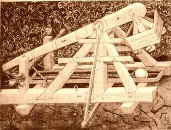
This
diagram of a similar model was found at Russell Miner’s website.
See the attached works cited page for more information. |
For the initial shooting portion of the project, we required our newly
build trebuchet, 120 pounds of lead weights, a half dozen 6 oz. apples, a stop
watch, a level field, and a 100ft. tape measure. That day we were unable to add
all the weight into the counter-weight bucket because the wooden dowel sounded
as if it would snap in half. So we only shot with about 70 lbs. With even this
little of weight, our counter-weight bucket broke on the second shot. After
being demoralized in front of Mr. Murray, we decided to change a few things. We
added a splint at the base of the arm to strengthen it, put plumber’s tape on
the box to allow for the weight, changed apples with baseballs because they are
much more uniform, and added paper shaving in with the lead weight to pack the
counter-weight box better, preventing the lead to bounce around inside. All of
these adjustments proved to be invaluable to the success of the trebuchet.
One of the biggest problems that we ran into during the creation of our final trebuchet was the seemingly simple sheer mechanics of holding the thing together. We assumed at first that simply by using thick screws, large bolts, thick wood, and more wood to reinforce that wood that the whole thing would hold together. In most places it fortunately did, however right from the beginning of our apple-launching stage we heard the arm cracking and the counterweight basket falling apart. In addition the makeshift c tag board slide that we had created was destroyed due to the elements and lead weights falling on it. After some initial patch work with duct tape we able later able to reinforce the basket with plumber’s tape and the dowel-arm with splints and plumber’s clamps. The cheap tag board slide was replaced with much more durable flashing.
Probably the largest difficulty that we ran into was the idea of how to release our projectile. We couldn’t at first find any viable way to attach the sling and have the projectile released. Naturally if the sling is attached is attached all the way around then our missile would fire directly into the ground. After some additional research we came up with the hanging nail method, where one end of the sling is permanently attached and the other is hung on a nail at the top of the arm. The nail is bent so that the sling is released and the projectile fired at a 45-degree angle.
On the day of our actual final testing, we gathered up all of our needed materials and positioned our trebuchet on an open field. We first took our 100-foot tape measure and measured it out all the way. At that 100 foot point we placed a large orange cone to mark that spot, and then stretched out the tape measure along the ground for the remainder of its range in order to get a horizontal spectrum that would be easy to measure distances on from 100 to 200 feet.
In order to prevent further cracking and breakage of our counterweight bucket we filled it up with both the lead weights and packed it with shredded paper in the fillings to brace it. This prevented the individual weights from gaining their own momentum and thus gain force against the basket, which only hinders our firing capabilities.
When we fired our machine it was a three-person operation, although more persons may be involved during a repetition of this experiment. The first person is the loader, who places the ammunition in the sling, hangs the sling on the nail, and loads the whole projectile and cloth portion of the sling on the slide. This first person is also the timer (a fourth person may be used for this). The timing is done from the point of release from the sling to the moment when it lands out in the field. The second person is the launcher. This person pulls back the arm while the loader loads, keeps the whole thing tight, and then naturally releases the whole thing. The third and last person stands out on the field with a block to mark where the projectile landed. It is the job of the marker to stand out in the field and wait for the object to come near him. When it did that guy dropped the block where he saw that the baseball landed, and then chase after the baseball in order to throw it back. We recorded all of our data points and then transferred them to Excel in order to better interpret the data. You can see in the attached raw data and the graphical interpretations certain trends that will be evaluated in the following section. TOP
A basic calculation that we made was finding the initial launch velocity of our projectiles. Basically when completing these operations I found both the initial vertical velocity and the initial horizontal velocity for each test launch. To find the starting horizontal velocity I simply took the total range of the object and divided it by the total time elapsed (ft/s). In finding the initial vertical velocity I used the formula (1/2)(g)(t), or –16 ft/s/s * time (s), which also results in ft/s. By taking the difference between these two calculations, I was able to determine how often and which trials were actually being fired at 45°. If in fact we were launching at 45°, then there would not be any difference at all, because the two numbers would be equal. I found that less than half (22 out of 49) trials actually had a difference within 10 ft/s, only 7 within 2 ft/s. The results of these and other calculations can be seen below.
|
|
Initial |
Initial |
|
Maximum |
Initial |
|
|
|
|
Horizontal
(ft/s) |
Vertical
(ft/s) |
Difference |
Height
(ft/s) |
Speed
(ft/s) |
Time
(s) |
Distance
(ft.) |
|
|
53.81791483 |
36.32 |
17.49791483 |
20.6116 |
64.92696171 |
2.27 |
122.1666667 |
|
|
51.54639175 |
31.04 |
20.50639175 |
15.0544 |
60.17069139 |
1.94 |
100 |
|
|
51.23318386 |
35.68 |
15.55318386 |
19.8916 |
62.4331765 |
2.23 |
114.25 |
|
|
50.07898894 |
33.76 |
16.31898894 |
17.8084 |
60.39571784 |
2.11 |
105.6666667 |
|
|
50.78320802 |
42.56 |
8.22320802 |
28.3024 |
66.25924703 |
2.66 |
135.0833333 |
|
|
50.37202381 |
35.84 |
14.53202381 |
20.0704 |
61.82108364 |
2.24 |
112.8333333 |
|
|
51.66015625 |
40.96 |
10.70015625 |
26.2144 |
65.92794054 |
2.56 |
132.25 |
|
|
53.29041488 |
37.28 |
16.01041488 |
21.7156 |
65.03588792 |
2.33 |
124.1666667 |
|
|
56.76470588 |
40.8 |
15.96470588 |
26.01 |
69.90616449 |
2.55 |
144.75 |
|
|
56.48148148 |
34.56 |
21.92148148 |
18.6624 |
66.21594483 |
2.16 |
122 |
|
|
52.91970803 |
43.84 |
9.079708029 |
30.0304 |
68.72001963 |
2.74 |
145 |
|
|
57.18954248 |
32.64 |
24.54954248 |
16.6464 |
65.84841205 |
2.04 |
116.6666667 |
|
|
53.68649318 |
43.04 |
10.64649318 |
28.9444 |
68.8090194 |
2.69 |
144.4166667 |
|
|
56.57679739 |
32.64 |
23.93679739 |
16.6464 |
65.31694728 |
2.04 |
115.4166667 |
|
|
30.25936599 |
55.52 |
-25.260634 |
48.1636 |
63.23052768 |
3.47 |
105 |
|
|
52.85087719 |
36.48 |
16.37087719 |
20.7936 |
64.21842119 |
2.28 |
120.5 |
|
|
51.52439024 |
39.36 |
12.16439024 |
24.2064 |
64.8380474 |
2.46 |
126.75 |
|
|
52.27001195 |
44.64 |
7.630011947 |
31.1364 |
68.73778982 |
2.79 |
145.8333333 |
|
|
54.93079585 |
46.24 |
8.690795848 |
33.4084 |
71.802019 |
2.89 |
158.75 |
|
|
48.1513083 |
46.88 |
1.271308305 |
34.3396 |
67.20329524 |
2.93 |
141.0833333 |
|
|
49.83198925 |
39.68 |
10.15198925 |
24.6016 |
63.70031046 |
2.48 |
123.5833333 |
|
|
50.82417582 |
43.68 |
7.144175824 |
29.8116 |
67.01521654 |
2.73 |
138.75 |
|
|
42.62345679 |
43.2 |
-0.57654321 |
29.16 |
60.68771761 |
2.7 |
115.0833333 |
|
|
51.3681592 |
32.16 |
19.2081592 |
16.1604 |
60.60489568 |
2.01 |
103.25 |
|
|
44.67353952 |
46.56 |
-1.88646048 |
33.8724 |
64.525644 |
2.91 |
130 |
|
|
48.62869198 |
37.92 |
10.70869198 |
22.4676 |
61.66584212 |
2.37 |
115.25 |
|
|
51.68957617 |
46.56 |
5.129576174 |
33.8724 |
69.56756345 |
2.91 |
150.4166667 |
|
|
47.91666667 |
39.04 |
8.876666667 |
23.8144 |
61.80718845 |
2.44 |
116.9166667 |
|
|
56.20300752 |
42.56 |
13.64300752 |
28.3024 |
70.49916066 |
2.66 |
149.5 |
|
|
45.77740492 |
47.68 |
-1.90259508 |
35.5216 |
66.09805747 |
2.98 |
136.4166667 |
|
|
52.40641711 |
29.92 |
22.48641711 |
13.9876 |
60.34599369 |
1.87 |
98 |
|
|
42.46506986 |
53.44 |
-10.9749301 |
44.6224 |
68.25771574 |
3.34 |
141.8333333 |
|
|
49.94026284 |
44.64 |
5.300262843 |
31.1364 |
66.98327741 |
2.79 |
139.3333333 |
|
|
51.44032922 |
38.88 |
12.56032922 |
23.6196 |
64.48070929 |
2.43 |
125 |
|
|
46.78184282 |
39.36 |
7.421842818 |
24.2064 |
61.13714434 |
2.46 |
115.0833333 |
|
|
50.53131991 |
47.68 |
2.851319911 |
35.5216 |
69.47515161 |
2.98 |
150.5833333 |
|
|
50.52083333 |
30.72 |
19.80083333 |
14.7456 |
59.12759931 |
1.92 |
97 |
|
|
50.46468401 |
43.04 |
7.424684015 |
28.9444 |
66.32590695 |
2.69 |
135.75 |
|
|
46.76806084 |
42.08 |
4.688060837 |
27.6676 |
62.91246231 |
2.63 |
123 |
|
|
47.0685112 |
40.48 |
6.588511199 |
25.6036 |
62.08119801 |
2.53 |
119.0833333 |
|
|
50.35161744 |
37.92 |
12.43161744 |
22.4676 |
63.03341795 |
2.37 |
119.3333333 |
|
|
53.04005722 |
37.28 |
15.76005722 |
21.7156 |
64.83090367 |
2.33 |
123.5833333 |
|
|
43.80144033 |
51.84 |
-8.03855967 |
41.9904 |
67.86716271 |
3.24 |
141.9166667 |
|
|
50.7020757 |
43.68 |
7.022075702 |
29.8116 |
66.92266343 |
2.73 |
138.4166667 |
|
|
49.16125541 |
49.28 |
-0.11874459 |
37.9456 |
69.60852989 |
3.08 |
151.4166667 |
|
|
40.99033816 |
55.2 |
-14.2096618 |
47.61 |
68.75498399 |
3.45 |
141.4166667 |
|
|
34.59725793 |
62.24 |
-27.6427421 |
60.5284 |
71.20946465 |
3.89 |
134.5833333 |
|
|
45.79124579 |
47.52 |
-1.72875421 |
35.2836 |
65.99233737 |
2.97 |
136 |
|
|
47.54738016 |
47.84 |
-0.29261984 |
35.7604 |
67.44938072 |
2.99 |
142.1666667 |
|
|
|
|
|
|
|
|
|
|
Average: |
49.59784546 |
41.88081633 |
7.717029132 |
28.15121633 |
65.40377376 |
2.61755102 |
128.2704082 |
In addition to the specified initial velocities and their differences calculations, I have included maximum heights, initial speeds, raw time, raw data distance, and the averages of all those data points. I found the maximum heights using the formula S = u*t + (1/2)*a*t^2, with u equal to the initial vertical velocity, acceleration equal to –32 ft/s/s, and of course half of the total time to get the projectile at mid-air. The initial speeds were found by taking the square root of the sum of the squares of both the initial vertical and horizontal velocities, or ((Vh^2) + (Vv^2))^(1/2). I also calculated the average time elapsed to be 2.618 seconds, and the average distance traveled to be 128.27 feet. A graph of the average heights from all trials versus a time scale gives and accurate picture of the normal path of our projectiles. See below graph.
Basically when looking at the scatter graph we see an upward trend in a linear relationship. Some data points didn’t follow this trend, spending much longer in the air while not going as far in distance. These points we simply figured to be errors, and they will be addressed more fully in the errors section. In the other graph you can clearly see the same trends as were expressed in our hypothesis. In this graph with two y-axes, it is easy to see that as one parameter goes up or down, the other logically follows. This is true in all but 2 of our data points, which are clearly visible because they occur where the two lines cross. It is important to notice that these points that are being thrown away were not fired at a 45° angle. It is crucial the study of this experiment to realize that if truly fired at a 45° angle, the line of best fit for the scatter graph would reveal a perfect linear relationship, which is exactly how one can tell that in our experiment we were not always able to replicate that angle with our hanging nail method. Please refer to the above “difference” calculations for the exact amount that these numbers were off by.
As far as for the interpretation of the remainder of our data, I would like to take a second to observe the actual relationship as far as they are conserved with linear kinematics. We had, for instance, originally hypothesized that a counterweight that was a hundred times greater than the projectile would be optimal. However, after much trial and error testing, it turned out that we used 81.5 pounds of counterweight to launch 5 oz baseballs, or .3125 lbs. This is actually 260.8 times the mass of the projectile. TOP
When measuring the errors and uncertainty included in our project, there are basically three areas in which we encountered possible problems where our results may have been skewed. First and foremost we have the slight problem with the human error of the person dropping the measuring block at the point of initial impact. Also the blocks often have a tendency to bounce; so that that when they finally come to rest they may not be where the baseball landed. We estimate that this could have varied up to .3 feet on each side. This uncertainty estimation also includes my second point of possible uncertainty of the tape measure itself, as it is stretched out on the field. It may not have been stretched out to exactly 200 feet. Lastly there is an assumed error in the actual timing of the projectile. This is mostly a human error. This problem is similar to the measuring error. I believe that a good estimate for this is to use about .2 seconds. We will have to include this estimation along with the distance error in determining an error spectrum. Basically we found the uncertainty value for both of the raw data parameters of time and distance to be as they were specified above: .2 seconds for the time and .3 feet for the distance. We then used these values to obtain some other calculated uncertainties. That is we took all of our raw data and found possible high and low values for our initial launch velocity. When calculating the lowest possible initial velocity we used the shortest distances possible covered in the greatest possible time, whereas to the get the high uncertainty value of initial velocity with took the greatest distance traveled in the least possible amount of time. All of the values that we obtained from these calculations can easily be seen in the data below. We also took the averages of these uncertainties, which are again seen in bold at the bottom of their respective column. Our average lowest possible initial launch horizontal velocity was determined to be 45.85198 ft/s while the highest average possible for horizontal we found to be 54.006 ft/s. For the vertical values we found the low to be 38.69 ft/s and the high to be 45.0808 ft/s.
|
|
|
|
|
Initial
High |
Initial
Low |
Initial
Low |
Initial
High |
|
Time |
Time |
Distance |
Distance |
Horizontal |
Horizontal |
Vertical |
Vertical |
|
Low |
High |
Low |
High |
Velocity |
Velocity |
Velocity |
Velocity |
|
2.07 |
2.47 |
121.8667 |
122.4667 |
49.33873144 |
59.1626409 |
33.12 |
39.52 |
|
1.74 |
2.14 |
99.7 |
100.3 |
46.58878505 |
57.64367816 |
27.84 |
34.24 |
|
2.03 |
2.43 |
113.95 |
114.55 |
46.89300412 |
56.42857143 |
32.48 |
38.88 |
|
1.91 |
2.31 |
105.3667 |
105.9667 |
45.61327561 |
55.47993019 |
30.56 |
36.96 |
|
2.46 |
2.86 |
134.7833 |
135.3833 |
47.12703963 |
55.03387534 |
39.36 |
45.76 |
|
2.04 |
2.44 |
112.5333 |
113.1333 |
46.12021858 |
55.45751634 |
32.64 |
39.04 |
|
2.36 |
2.76 |
131.95 |
132.55 |
47.80797101 |
56.16525424 |
37.76 |
44.16 |
|
2.13 |
2.53 |
123.8667 |
124.4667 |
48.95915679 |
58.43505477 |
34.08 |
40.48 |
|
2.35 |
2.75 |
144.45 |
145.05 |
52.52727273 |
61.72340426 |
37.6 |
44 |
|
1.96 |
2.36 |
121.7 |
122.3 |
51.56779661 |
62.39795918 |
31.36 |
37.76 |
|
2.54 |
2.94 |
144.7 |
145.3 |
49.21768707 |
57.20472441 |
40.64 |
47.04 |
|
1.84 |
2.24 |
116.3667 |
116.9667 |
51.94940476 |
63.56884058 |
29.44 |
35.84 |
|
2.49 |
2.89 |
144.1167 |
144.7167 |
49.86735871 |
58.11914324 |
39.84 |
46.24 |
|
1.84 |
2.24 |
115.1167 |
115.7167 |
51.39136905 |
62.88949275 |
29.44 |
35.84 |
|
3.27 |
3.67 |
104.7 |
105.3 |
28.52861035 |
32.20183486 |
52.32 |
58.72 |
|
2.08 |
2.48 |
120.2 |
120.8 |
48.46774194 |
58.07692308 |
33.28 |
39.68 |
|
2.26 |
2.66 |
126.45 |
127.05 |
47.53759398 |
56.21681416 |
36.16 |
42.56 |
|
2.59 |
2.99 |
145.5333 |
146.1333 |
48.67335563 |
56.42213642 |
41.44 |
47.84 |
|
2.69 |
3.09 |
158.45 |
159.05 |
51.27831715 |
59.12639405 |
43.04 |
49.44 |
|
2.73 |
3.13 |
140.7833 |
141.3833 |
44.97870075 |
51.78876679 |
43.68 |
50.08 |
|
2.28 |
2.68 |
123.2833 |
123.8833 |
46.00124378 |
54.33479532 |
36.48 |
42.88 |
|
2.53 |
2.93 |
138.45 |
139.05 |
47.25255973 |
54.96047431 |
40.48 |
46.88 |
|
2.5 |
2.9 |
114.7833 |
115.3833 |
39.58045977 |
46.15333333 |
40 |
46.4 |
|
1.81 |
2.21 |
102.95 |
103.55 |
46.58371041 |
57.20994475 |
28.96 |
35.36 |
|
2.71 |
3.11 |
129.7 |
130.3 |
41.70418006 |
48.08118081 |
43.36 |
49.76 |
|
2.17 |
2.57 |
114.95 |
115.55 |
44.72762646 |
53.24884793 |
34.72 |
41.12 |
|
2.71 |
3.11 |
150.1167 |
150.7167 |
48.26902465 |
55.61500615 |
43.36 |
49.76 |
|
2.24 |
2.64 |
116.6167 |
117.2167 |
44.1729798 |
52.32886905 |
35.84 |
42.24 |
|
2.46 |
2.86 |
149.2 |
149.8 |
52.16783217 |
60.89430894 |
39.36 |
45.76 |
|
2.78 |
3.18 |
136.1167 |
136.7167 |
42.80398323 |
49.17865707 |
44.48 |
50.88 |
|
1.67 |
2.07 |
97.7 |
98.3 |
47.19806763 |
58.86227545 |
26.72 |
33.12 |
|
3.14 |
3.54 |
141.5333 |
142.1333 |
39.98116761 |
45.26539278 |
50.24 |
56.64 |
|
2.59 |
2.99 |
139.0333 |
139.6333 |
46.49944259 |
53.91248391 |
41.44 |
47.84 |
|
2.23 |
2.63 |
124.7 |
125.3 |
47.41444867 |
56.18834081 |
35.68 |
42.08 |
|
2.26 |
2.66 |
114.7833 |
115.3833 |
43.15162907 |
51.05457227 |
36.16 |
42.56 |
|
2.78 |
3.18 |
150.2833 |
150.8833 |
47.25890985 |
54.27458034 |
44.48 |
50.88 |
|
1.72 |
2.12 |
96.7 |
97.3 |
45.61320755 |
56.56976744 |
27.52 |
33.92 |
|
2.49 |
2.89 |
135.45 |
136.05 |
46.86851211 |
54.63855422 |
39.84 |
46.24 |
|
2.43 |
2.83 |
122.7 |
123.3 |
43.35689046 |
50.74074074 |
38.88 |
45.28 |
|
2.33 |
2.73 |
118.7833 |
119.3833 |
43.51037851 |
51.23748212 |
37.28 |
43.68 |
|
2.17 |
2.57 |
119.0333 |
119.6333 |
46.31647211 |
55.13056836 |
34.72 |
41.12 |
|
2.13 |
2.53 |
123.2833 |
123.8833 |
48.72859025 |
58.16118936 |
34.08 |
40.48 |
|
3.04 |
3.44 |
141.6167 |
142.2167 |
41.16763566 |
46.78179825 |
48.64 |
55.04 |
|
2.53 |
2.93 |
138.1167 |
138.7167 |
47.13879408 |
54.828722 |
40.48 |
46.88 |
|
2.88 |
3.28 |
151.1167 |
151.7167 |
46.07215447 |
52.67939815 |
46.08 |
52.48 |
|
3.25 |
3.65 |
141.1167 |
141.7167 |
38.66210046 |
43.60512821 |
52 |
58.4 |
|
3.69 |
4.09 |
134.2833 |
134.8833 |
32.83211084 |
36.55374887 |
59.04 |
65.44 |
|
2.77 |
3.17 |
135.7 |
136.3 |
42.80757098 |
49.20577617 |
44.32 |
50.72 |
|
2.79 |
3.19 |
141.8667 |
142.4667 |
44.4723093 |
51.06332139 |
44.64 |
51.04 |
|
|
|
|
|
|
|
|
|
|
2.4176 |
2.81755 |
127.9704 |
128.5704 |
45.85198741 |
54.00616763 |
38.68081633 |
45.08081633 |
Now, that finally brings us to our conclusion. This project turned out by unanimous vote to be the most challenging yet exciting science project that we have ever worked on. We learned a great deal in our exploration of research, through the successes and failures of building, and of the science and math behind such a complicated endeavor. This project, which has spanned over four months, encountered many problems left and right, as they were of course explained previously.
We would however happily conclude that our original hypothesis did in fact hold up in the end. When looking at the trends of both of the attached graphs, this becomes clearly apparent. All one must do is make sure to throw out the two outlying data points when observing these points for the reasons stipulated above in the uncertainty. I would also like to point out our use of calculating the initial velocity as key to our conclusion. By observing values that actually fell near the 45-degree parameter, and showing that those data points had similar initial vertical and horizontal velocities, it becomes clear that our machine and our procedure is viable because in naturally follows the laws of physics. Calculating these values is a test to our method. If it were not in working order, then we would derive values that are completely incoherent with standard laws of motion. It is crucial to our study of trebuchets to learn how to best achieve an optimal firing angle, and via this experiment it is self evident that the hanging-nail model is a poor way to find a perfectly static launch angle. We did however achieve fairly good success in achieving a constant enough firing angle that for all but two data points we were able to prove hang time was related to total distance traveled. TOP
Word
Count: 3980
Toms, Ron. “Dedicated to the Art of Hurling.” October 2002.
This site is basically dedicated to the whole are of at home hurling in your own backyard from the retail perspective. They are in the business of selling trebuchets and other various little fun things, that could of course be used in a detailed physics project like this. Cheap and industrious as we are, however, we just "eye-copied" their designs and built our own.
Miners, Russell. “The Grey Company Trebuchet Page.” February 2000.
This site truly loves the trebuchet. It filled and/or packed with fun filled little factoids on the beautiful machines, as well as many pictures. Again, we used their designs in the planning of our own.
http://members.iinet.net.au/~rmine/gctrebs.html
Miners. Russell. “Cheesechucker – a trebuchet.” 1996
Ultimately it was this mini counter-weight treb, dubbed "Cheesechucker" that we used as the specs for our own, larger scale version.
http://members.iinet.net.au/~rmine/cheese.html
Fuzzball Software. “Trebuchet Home Page and Trebuchet FAQ.” 1998.
Honestly, this page isn't all that helpful, except of course for as it says FAQ. Again is has some good little tidbits of information for the background section of our project.
http://www.belfry.com/fuzzball/trebuchet/
Radlinski, Filip. “Welcome to the Physics of the Trebuchet.” 1997.
This site is what you would call the same category as the one your reading now. It is dedicated to a guy's physics class report that he id on a trebuchet. Also, he did a very good job, so you should check it out.
http://www.geocities.com/SiliconValley/Park/6461/trebuch.html
Siano, Donald B. “The Algorithmic Beauty of the Trebuchet.” 12, April 2002.
This site is very interesting, but not necessarily all that helpful. Check it out if you like, you'll see what I mean.
http://www.algobeautytreb.com/
Carlisle, Paul. “The Trebuchet.” February 1, 1998.
Man, this guy really loves his trebuchets. That's all. I really don't have anything more to say about his site. It has more additional information that was repeated on the previous ones...check it out if you want.
http://www.ameritech.net/users/paulcarlisle/trebuchet.html